Feeds:
Posts
Comments

Archive for the ‘Bio-MEMS’ Category

Cancer Genomics: Multiomic Analysis of Single Cells and Tumor Heterogeneity

Curator: Stephen J. Williams, PhD

4.3.7

4.3.7 Cancer Genomics: Multiomic Analysis of Single Cells and Tumor Heterogeneity, Volume 2 (Volume Two: Latest in Genomics Methodologies for Therapeutics: Gene Editing, NGS and BioInformatics, Simulations and the Genome Ontology), Part 4: Single Cell Genomics

scTrio-seq identifies colon cancer lineages

Single-cell multiomics sequencing and analyses of human colorectal cancer. Shuhui Bian et al. Science  30 Nov 2018:Vol. 362, Issue 6418, pp. 1060-1063

To better design treatments for cancer, it is important to understand the heterogeneity in tumors and how this contributes to metastasis. To examine this process, Bian et al. used a single-cell triple omics sequencing (scTrio-seq) technique to examine the mutations, transcriptome, and methylome within colorectal cancer tumors and metastases from 10 individual patients. The analysis provided insights into tumor evolution, linked DNA methylation to genetic lineages, and showed that DNA methylation levels are consistent within lineages but can differ substantially among clones.

Science, this issue p. 1060

Abstract

Although genomic instability, epigenetic abnormality, and gene expression dysregulation are hallmarks of colorectal cancer, these features have not been simultaneously analyzed at single-cell resolution. Using optimized single-cell multiomics sequencing together with multiregional sampling of the primary tumor and lymphatic and distant metastases, we developed insights beyond intratumoral heterogeneity. Genome-wide DNA methylation levels were relatively consistent within a single genetic sublineage. The genome-wide DNA demethylation patterns of cancer cells were consistent in all 10 patients whose DNA we sequenced. The cancer cells’ DNA demethylation degrees clearly correlated with the densities of the heterochromatin-associated histone modification H3K9me3 of normal tissue and those of repetitive element long interspersed nuclear element 1. Our work demonstrates the feasibility of reconstructing genetic lineages and tracing their epigenomic and transcriptomic dynamics with single-cell multiomics sequencing.

Fig. 1 Reconstruction of genetic lineages with scTrio-seq2.

Global SCNA patterns (250-kb resolution) of CRC01. Each row represents an individual cell. The subclonal SCNAs used for identifying genetic sublineages were marked and indexed; for details, see fig. S6B. On the top of the heatmap, the amplification or deletion frequency of each genomic bin (250 kb) of the non-hypermutated CRC samples from the TCGA Project and patient CRC01’s cancer cells are shown.

” data-icon-position=”” data-hide-link-title=”0″>

Fig. 1 Reconstruction of genetic lineages with scTrio-seq2.

Global SCNA patterns (250-kb resolution) of CRC01. Each row represents an individual cell. The subclonal SCNAs used for identifying genetic sublineages were marked and indexed; for details, see fig. S6B. On the top of the heatmap, the amplification or deletion frequency of each genomic bin (250 kb) of the non-hypermutated CRC samples

Read Full Post »

Use of 3D Bioprinting for Development of Toxicity Prediction Models

Curator: Stephen J. Williams, PhD

SOT FDA Colloquium on 3D Bioprinted Tissue Models: Tuesday, April 9, 2019

The Society of Toxicology (SOT) and the U.S. Food and Drug Administration (FDA) will hold a workshop on “Alternative Methods for Predictive Safety Testing: 3D Bioprinted Tissue Models” on Tuesday, April 9, at the FDA Center for Food Safety and Applied Nutrition in College Park, Maryland. This workshop is the latest in the series, “SOT FDA Colloquia on Emerging Toxicological Science: Challenges in Food and Ingredient Safety.”

Human 3D bioprinted tissues represent a valuable in vitro approach for chemical, personal care product, cosmetic, and preclinical toxicity/safety testing. Bioprinting of skin, liver, and kidney is already appearing in toxicity testing applications for chemical exposures and disease modeling. The use of 3D bioprinted tissues and organs may provide future alternative approaches for testing that may more closely resemble and simulate intact human tissues to more accurately predict human responses to chemical and drug exposures.

A synopsis of the schedule and related works from the speakers is given below:


8:40 AM–9:20 AM Overview and Challenges of Bioprinting
Sharon Presnell, Amnion Foundation, Winston-Salem, NC
9:20 AM–10:00 AM Putting 3D Bioprinting to the Use of Tissue Model Fabrication
Y. Shrike Zhang, Brigham and Women’s Hospital, Harvard Medical School and Harvard-MIT Division of Health Sciences and Technology, Boston, MA
10:00 AM–10:20 AM Break
10:20 AM–11:00 AM Uses of Bioprinted Liver Tissue in Drug Development
Jean-Louis Klein, GlaxoSmithKline, Collegeville, PA
11:00 AM–11:40 AM Biofabrication of 3D Tissue Models for Disease Modeling and Chemical Screening
Marc Ferrer, National Center for Advancing Translational Sciences, NIH, Rockville, MD

Sharon Presnell, Ph.D. President, Amnion Foundation

Dr. Sharon Presnell was most recently the Chief Scientific Officer at Organovo, Inc., and the President of their wholly-owned subsidiary, Samsara Sciences. She received a Ph.D. in Cell & Molecular Pathology from the Medical College of Virginia and completed her undergraduate degree in biology at NC State. In addition to her most recent roles, Presnell has served as the director of cell biology R&D at Becton Dickinson’s corporate research center in RTP, and as the SVP of R&D at Tengion. Her roles have always involved the commercial and clinical translation of basic research and early development in the cell biology space. She serves on the board of the Coulter Foundation at the University of Virginia and is a member of the College of Life Sciences Foundation Board at NC State. In January 2019, Dr. Presnell will begin a new role as President of the Amnion Foundation, a non-profit organization in Winston-Salem.

A few of her relevant publications:

Bioprinted liver provides early insight into the role of Kupffer cells in TGF-β1 and methotrexate-induced fibrogenesis

Integrating Kupffer cells into a 3D bioprinted model of human liver recapitulates fibrotic responses of certain toxicants in a time and context dependent manner.  This work establishes that the presence of Kupffer cells or macrophages are important mediators in fibrotic responses to certain hepatotoxins and both should be incorporated into bioprinted human liver models for toxicology testing.

Bioprinted 3D Primary Liver Tissues Allow Assessment of Organ-Level Response to Clinical Drug Induced Toxicity In Vitro

Abstract: Modeling clinically relevant tissue responses using cell models poses a significant challenge for drug development, in particular for drug induced liver injury (DILI). This is mainly because existing liver models lack longevity and tissue-level complexity which limits their utility in predictive toxicology. In this study, we established and characterized novel bioprinted human liver tissue mimetics comprised of patient-derived hepatocytes and non-parenchymal cells in a defined architecture. Scaffold-free assembly of different cell types in an in vivo-relevant architecture allowed for histologic analysis that revealed distinct intercellular hepatocyte junctions, CD31+ endothelial networks, and desmin positive, smooth muscle actin negative quiescent stellates. Unlike what was seen in 2D hepatocyte cultures, the tissues maintained levels of ATP, Albumin as well as expression and drug-induced enzyme activity of Cytochrome P450s over 4 weeks in culture. To assess the ability of the 3D liver cultures to model tissue-level DILI, dose responses of Trovafloxacin, a drug whose hepatotoxic potential could not be assessed by standard pre-clinical models, were compared to the structurally related non-toxic drug Levofloxacin. Trovafloxacin induced significant, dose-dependent toxicity at clinically relevant doses (≤ 4uM). Interestingly, Trovafloxacin toxicity was observed without lipopolysaccharide stimulation and in the absence of resident macrophages in contrast to earlier reports. Together, these results demonstrate that 3D bioprinted liver tissues can both effectively model DILI and distinguish between highly related compounds with differential profile. Thus, the combination of patient-derived primary cells with bioprinting technology here for the first time demonstrates superior performance in terms of mimicking human drug response in a known target organ at the tissue level.

A great interview with Dr. Presnell and the 3D Models 2017 Symposium is located here:

Please click here for Web based and PDF version of interview

Some highlights of the interview include

  • Exciting advances in field showing we can model complex tissue-level disease-state phenotypes that develop in response to chronic long term injury or exposure
  • Sees the field developing a means to converge both the biology and physiology of tissues, namely modeling the connectivity between tissues such as fluid flow
  • Future work will need to be dedicated to develop comprehensive analytics for 3D tissue analysis. As she states “we are very conditioned to get information in a simple way from biochemical readouts in two dimension, monocellular systems”  however how we address the complexity of various cellular responses in a 3D multicellular environment will be pertinent.
  • Additional challenges include the scalability of such systems and making such system accessible in a larger way
  1. Shrike Zhang, Brigham and Women’s Hospital, Harvard Medical School and Harvard-MIT Division of Health Sciences and Technology

Dr. Zhang currently holds an Assistant Professor position at Harvard Medical School and is an Associate Bioengineer at Brigham and Women’s Hospital. His research interests include organ-on-a-chip, 3D bioprinting, biomaterials, regenerative engineering, biomedical imaging, biosensing, nanomedicine, and developmental biology. His scientific contributions have been recognized by >40 international, national, and regional awards. He has been invited to deliver >70 lectures worldwide, and has served as reviewer for >400 manuscripts for >30 journals. He is serving as Editor-in-Chief for Microphysiological Systems, and Associate Editor for Bio-Design and Manufacturing. He is also on Editorial Board of BioprintingHeliyonBMC Materials, and Essays in Biochemistry, and on Advisory Panel of Nanotechnology.

Some relevant references from Dr. Zhang

Multi-tissue interactions in an integrated three-tissue organ-on-a-chip platform.

Skardal A, Murphy SV, Devarasetty M, Mead I, Kang HW, Seol YJ, Shrike Zhang Y, Shin SR, Zhao L, Aleman J, Hall AR, Shupe TD, Kleensang A, Dokmeci MR, Jin Lee S, Jackson JD, Yoo JJ, Hartung T, Khademhosseini A, Soker S, Bishop CE, Atala A.

Sci Rep. 2017 Aug 18;7(1):8837. doi: 10.1038/s41598-017-08879-x.


Reconstruction of Large-scale Defects with a Novel Hybrid Scaffold Made from Poly(L-lactic acid)/Nanohydroxyapatite/Alendronate-loaded Chitosan Microsphere: in vitro and in vivo Studies.

Wu H, Lei P, Liu G, Shrike Zhang Y, Yang J, Zhang L, Xie J, Niu W, Liu H, Ruan J, Hu Y, Zhang C.

Sci Rep. 2017 Mar 23;7(1):359. doi: 10.1038/s41598-017-00506-z.


A liver-on-a-chip platform with bioprinted hepatic spheroids.

Bhise NS, Manoharan V, Massa S, Tamayol A, Ghaderi M, Miscuglio M, Lang Q, Shrike Zhang Y, Shin SR, Calzone G, Annabi N, Shupe TD, Bishop CE, Atala A, Dokmeci MR, Khademhosseini A.

Biofabrication. 2016 Jan 12;8(1):014101. doi: 10.1088/1758-5090/8/1/014101.


Marc Ferrer, National Center for Advancing Translational Sciences, NIH

Marc Ferrer is a team leader in the NCATS Chemical Genomics Center, which was part of the National Human Genome Research Institute when Ferrer began working there in 2010. He has extensive experience in drug discovery, both in the pharmaceutical industry and academic research. Before joining NIH, he was director of assay development and screening at Merck Research Laboratories. For 10 years at Merck, Ferrer led the development of assays for high-throughput screening of small molecules and small interfering RNA (siRNA) to support programs for lead and target identification across all disease areas.

At NCATS, Ferrer leads the implementation of probe development programs, discovery of drug combinations and development of innovative assay paradigms for more effective drug discovery. He advises collaborators on strategies for discovering small molecule therapeutics, including assays for screening and lead identification and optimization. Ferrer has experience implementing high-throughput screens for a broad range of disease areas with a wide array of assay technologies. He has led and managed highly productive teams by setting clear research strategies and goals and by establishing effective collaborations between scientists from diverse disciplines within industry, academia and technology providers.

Ferrer has a Ph.D. in biological chemistry from the University of Minnesota, Twin Cities, and completed postdoctoral training at Harvard University’s Department of Molecular and Cellular Biology. He received a B.Sc. degree in organic chemistry from the University of Barcelona in Spain.


Some relevant references for Dr. Ferrer

Fully 3D Bioprinted Skin Equivalent Constructs with Validated Morphology and Barrier Function.

Derr K, Zou J, Luo K, Song MJ, Sittampalam GS, Zhou C, Michael S, Ferrer M, Derr P.

Tissue Eng Part C Methods. 2019 Apr 22. doi: 10.1089/ten.TEC.2018.0318. [Epub ahead of print]


Determination of the Elasticity Modulus of 3D-Printed Octet-Truss Structures for Use in Porous Prosthesis Implants.

Bagheri A, Buj-Corral I, Ferrer M, Pastor MM, Roure F.

Materials (Basel). 2018 Nov 29;11(12). pii: E2420. doi: 10.3390/ma11122420.


Mutation Profiles in Glioblastoma 3D Oncospheres Modulate Drug Efficacy.

Wilson KM, Mathews-Griner LA, Williamson T, Guha R, Chen L, Shinn P, McKnight C, Michael S, Klumpp-Thomas C, Binder ZA, Ferrer M, Gallia GL, Thomas CJ, Riggins GJ.

SLAS Technol. 2019 Feb;24(1):28-40. doi: 10.1177/2472630318803749. Epub 2018 Oct 5.


A high-throughput imaging and nuclear segmentation analysis protocol for cleared 3D culture models.

Boutin ME, Voss TC, Titus SA, Cruz-Gutierrez K, Michael S, Ferrer M.

Sci Rep. 2018 Jul 24;8(1):11135. doi: 10.1038/s41598-018-29169-0.

A High-Throughput Screening Model of the Tumor Microenvironment for Ovarian Cancer Cell Growth.

Lal-Nag M, McGee L, Guha R, Lengyel E, Kenny HA, Ferrer M.

SLAS Discov. 2017 Jun;22(5):494-506. doi: 10.1177/2472555216687082. Epub 2017 Jan 31.


Exploring Drug Dosing Regimens In Vitro Using Real-Time 3D Spheroid Tumor Growth Assays.

Lal-Nag M, McGee L, Titus SA, Brimacombe K, Michael S, Sittampalam G, Ferrer M.

SLAS Discov. 2017 Jun;22(5):537-546. doi: 10.1177/2472555217698818. Epub 2017 Mar 15.


RNAi High-Throughput Screening of Single- and Multi-Cell-Type Tumor Spheroids: A Comprehensive Analysis in Two and Three Dimensions.

Fu J, Fernandez D, Ferrer M, Titus SA, Buehler E, Lal-Nag MA.

SLAS Discov. 2017 Jun;22(5):525-536. doi: 10.1177/2472555217696796. Epub 2017 Mar 9.


Other Articles on 3D Bioprinting on this Open Access Journal include:

Global Technology Conferences on 3D BioPrinting 2015 – 2016

3D Medical BioPrinting Technology Reporting by Irina Robu, PhD – a forthcoming Article in “Medical 3D BioPrinting – The Revolution in Medicine, Technologies for Patient-centered Medicine: From R&D in Biologics to New Medical Devices”

Bio-Inks and 3D BioPrinting

New Scaffold-Free 3D Bioprinting Method Available to Researchers

Gene Editing for Gene Therapies with 3D BioPrinting


Read Full Post »

What could replace animal testing – ‘Human-on-a-chip’ from Lawrence Livermore National Laboratory

The iCHIP research, Moya said, could have implications for creating new drugs to fight cancer, vaccines or evaluating the efficacy of countermeasures against biowarfare agents.

Lab scientist Heather Enright is leading research into the peripheral nervous system (PNS), which connects the brain to the limbs and organs. The PNS device has arrays of microelectrodes embedded on glass, where primary human dorsal root ganglion (DRG) neurons are seeded. Chemical stimuli such as capsaicin (to study pain response) then flow through a microfluidic cap to stimulate the cells on the platform.

The microelectrodes record electrical signals from the cells, allowing researchers to determine how the cells are responding to the stimuli non-invasively. Microscopic images can be acquired at the same time to monitor changes in intracellular ion concentrations, such as calcium. This platform is the first to demonstrate that long-term culture and chemical interrogation of primary human DRG neurons on microelectrode arrays is possible, presenting researchers with an advantage over current techniques.

Read full article at the SOURCE


http://universityofcalifornia.edu/news/human-chip-could-replace-animal-testing

Read Full Post »

Ions, molecules, and bio-markers measurements using BioMEMS

Curator: Danut Dragoi, PhD


Small or large molecules and ions are traditionally determined in specific clinical labs facilities utilizing complex instrumentation and standard operation procedures. Same analytical clinical results can be obtained today from specialized miniaturized bioMEMS. The miniaturized instrumentation and procedures use less sample and highly sophisticated algorithms for data processing, usually intended without sample preparation or lengthy time analysis. These features reduce the costs associated with the lab work, provide rapid results to the patient and doctors. In this presentation, the talk is focused on  ions, molecules, and bio-markers measurements using BioMEMS as shown in the first slide.

Slide1

Slide #2

An overview of the presentation includes the items shown below.

Slide2

Slide #3 shows a palm size DNA and RNA sequencer, see link in here, that I assume astronaut Scot Kelly recently used in outer space, International Space Station,  to monitor his DNA and RNA changes as an effect of low gravitation and cosmic radiation, during his close to one year work in outer space. The tiny new device shown in the picture below called the MinION™, is developed by Oxford Nanopore Technologies, promises to help scientists sequence DNA in space. NASA’s Biomolecule Sequencer investigation is a technology demonstration of the device.

Slide3

Slide #4

The physical principle of the DNA sequencer is based on the perturbation of the electric current that flows trough the nanopore plate when one strand of DNA macromolecule, with nucleotides attached, goes through a small pore of 5 nm diameter. In this way, by recording the electrical signals, the genetic code is revealed, see link in here.

Slide4


Slide #5

The picture in slide #5 taken from here, shows how the physical principle explained before is applied.


Slide5

Slide #6

The one-strip bio-sensor structure, common for glucose concentration measurements shows three layers of electrodes, see link in here, that provide an electrical signal proportional to the amount of glucose in a tiny amount of blood.

Slide6

Slide #7

This slide explains the principle and the chemical reaction at the electrodes for a common glucosometer, see link in here.

Slide7

Slide #8

The principle of glucosometer can be applied to other molecules, such as bio-markers that represent large molecules associated with an antigen tumor in human plasma, see link in here.  Photo image below is for a portable strip reader.

Slide8

Slide #9

The chemical reactions specific to a glucose meter, shown bellow, are taken from here.

Slide9

Slide #10

The schematic below shows how one strip biosensor for bio-markers works, see link in here. The complexity of a bio-marker molecule requires conditional measurements for accuracy and reproducible results.

Slide10

Slide #11

The schematic below is a continuation of slide #10 in which standard bio-markers are introduced in order to have a comparison between a test line and a control line besides additional antigens, gold antigen conjugate, and antibodies.Details of how all these markers interact on the strip biosensor, see link in here.

Slide11

Slide #12

In this slide, which is a continuation of slides #10 and slide #11, the goat anti-mouse IgG is introduced as a control sample in the control line.

Slide12

Slide #13

In many situations, one strip amperometric (electrical current) is not enough to perform the measurements, as in salt daily intake determination, see link in here.The analyte in this case is determined from the analysis of an image taken from the strips, see link in here.

Slide13

Slide #14

The technique described in here, has two strips for measurements. In this way the ions in human body fluids, like Na+ can be successfully determined utilizing BioMEMS such as that described in here, and here.

Slide14

Slide #15

NB-Inspired from Na+ ions determination, a possibility of similar measurements exists for K+ ions.

Slide15


Slide #17

Slide #17 introduces the long range surface plasmon polariton (LRSPP) technique , which is similar to surface enhanced Raman scattering (SERS) technique. When the sample is functionalized with G protein than the interaction between components is reflected in the optical cavity power measurements, which is exploited on determining the ratio of light kappa and lambda polymeric chains.

Slide17

Slide #18

The slide shows an optical plasmonic biosensor for leukemia detection, see link in here.


Slide_18

Slide #19

The schematic on slide #19 shows how specificity of protein G, human IgG kappa and lambda, goat anti-human IgG kappa and lambda as pure standards work on optical plasmonic method.

Slide19

Slide#20

The output optical power of the LRSPP device versus time of introducing the analyte and the standards shows specific signal shifts for anti-human lambda IgG on HKS (high kappa serum) and anti-human kappa IgG on HKS.  If the ratio of the two signal is outside of a small given range, see link in here, than the measurements indicate the presence of  the cancer cells.

Slide20

Slide #21

This slide shows the description of chemiluminescence method applied on a chip, see link in here, that become more popular with the development of measurements on micro-fluids using sensitive photo detectors arrays.

Slide21

Slide #22

The schematic below, taken from here, shows three sections of the chip, in which tiny capillaries lines take the sample without micro-pumping using the capillary effect, separates the light molecules from the heavy, and bring them in an area where chemiluminiscent effect takes place, emitted photons detected by an array of sensitive detectors and their signal electronically processed.

Slide22

Slide #23

This slide highlights the detection process that takes place towards the end of the capillary, see link in here.

Slide23

Slide #24

This slide illustrates a sample of signals adapted from a photo-detector array, see link in here.

Slide24

Slide #25

In conclusion, heavy analytes of bio samples can be determined with BioMEMS based chemiluminescence effect, many analyte solutions can get through a relative long capillary path using BioMEMS that are prone to miniaturization. The method of detecting photons from analyte interaction with a bioenzime-substrate with mono and multi-strips trend to be the generalization of actual R & D miniaturized devices. The new analytical micro-devices based on sensitive photo-detectors array reduces the actual costs of clinical analyzes and increases the speed of analytical process.

Slide25

Source

http://www.saltcounts.com/

https://www.nanoporetech.com/community/start-using-minion

http://www.nasa.gov/centers/ames/research/technology-onepagers/nanopores_gene_sequencing.html

Click to access amperometric-test-strips-for-point-of-care-biosensors-an-overview.pdf

Click to access AJBMS_2009_1_07.pdf

http://spie.org/newsroom/technical-articles/6268-optical-plasmonic-biosensor-for-leukemia-detection?ArticleID=x116720

https://sites.google.com/site/inescmn/home/research/mems-and-lab-on-chip-devices/lab-on-chip-devices


Read Full Post »

Medical MEMS, BioMEMS and Sensor Applications

Curator and Reporter: Aviva Lev-Ari, PhD, RN


Contents for Chapter 11

Medical MEMS, BioMEMS and Sensors Applications

Curators: Justin D. Pearlman, MD, PhD, FACC, LPBI Group, Danut Dragoi, PhD, LPBI Group and William H. Zurn, Alpha IP

FOR

Series E: Patient-centered Medicine

Volume 4:  Medical 3D BioPrinting – The Revolution in Medicine

Editors: Larry H Bernstein, MD FCAP and Aviva Lev-Ari, PhD, RN

http://pharmaceuticalintelligence.com/biomed-e-books/series-e-titles-in-the-strategic-plan-for-2014-1015/volume-four-medical-3d-bioprinting-the-revolution-in-medicine/

Work-in-Progress

ContactLens

Image Source

http://www.memsjournal.com/2010/05/medical-applications-herald-third-wave-of-mems.html

Image is courtesy of Google Images


WirelessPressure

Image Source

Stanford Engineering Team Invents Pressure Sensor That Uses Radio Waves | CytoFluidix

Image is courtesy of Google Images


Introduction by Dr. Pearlman


Chapter 1: Blood Glucose Sensors

1.1       MINIATURIZED GLUCOSE SENSOR – Google

  • Tiny wireless chip and miniaturized glucose sensor
  • Embedded between two layers of soft contact lens material
  • Accurate glucose monitoring for diabetics
  • Using bodily fluids, i.e. tears
  • Prototypes can generate one reading per second
  • Experimenting with LEDs
  • Early warning for the wearer


Chapter 2: Blood Chemistry Tests – up to 100 Samples

2.1       NON-INVASIVE BLOOD MONITOR- UCSD

  • Digital tattoo monitors blood below the skin
  • Tattoos are needle-less
    • Sensor-laden transdermal patch
  • Painless for the user Tiny sensors “ink”
  • Can read blood levels of:
    • Sodium, glucose, kidney function
  • Prototypes contain probes
  • Wireless, battery-powered chip
  • Continually test up to a hundred different samples


2.3       CELLPHONE-BASED RAPID-DIAGNOSTIC-TEST (RDT) READER – UCLA

  • Lateral flow immuno-chromatographic assays
  • Sense the presence of a target analyte in a sample
  • Device connects to the camera on a cell phone
  • Weighs only 65 grams


2.4       IMPLANTABLE BLOOD ANALYZER CHIP – EPFL

  • Implantable device for instantaneous blood analysis
  • Wireless data transmission to a doctor
  • Applications include monitoring general health
  • Tailor drug delivery to a patient’s unique needs
  • Includes five sensors and a radio transmitter
  • Powered via inductive coupling from a battery patch
  • Worn outside the body


Chapter 3: Motion Sensors for Head-Impact

3.1       HEAD-IMPACT MONITORING PATCH – STMicro & X2Biosystems

  • Wearable electronic contains MEMS motion sensors
  • Microcontroller, low-power radio transmitter, and power management circuitry
  • Cloud-based system combines athlete concussion history
  • Pre-season neurocognitive function, balance, and coordinate-performance data
  • Creates a baseline for comparison after a suspected injury event


Chapter 4: Drug Delivery & Drug Compliance Monitoring Systems

4.1       Smart Pill delivers Therapeutic Agent Load to target – ELECTRONIC PILL – Phillips

  • Electronic pill to treat gastrointestinal cancer
  • An ingestible pill is swallowed by the patient, finds its way to the tumor, dispenses the drugs and passes harmlessly from the body
  • Smart pill contains reservoir for drug supply, fluid pump for drug delivery, pH sensor (for navigation), thermometer, microprocessor, communication


4.2       Drug Compliance Monitoring Systems

4.2.1    INGESTIBLE BIOMEDICAL SENSOR – Proteus Digital Health

  • Biomedical sensor that monitors medication adherence
  • Embedded into a pill, the sensor is activated by stomach fluid
  • Transmits a signal through the body to a skin patch
  • Indicates whether a patient has ingested material


4.2.2    MICROPUMP DEVICES – Purdue University

  • Device based on skin contact actuation for drug delivery
  • Actuation mechanism only requires body heat
  • Induced actuation can result to a gradient of 100 Pa/oC
  • Sufficient to drive liquid drug through micro-needle arrays
  • Prototypes exhibit low fabrication costs, employment of biocompatible materials and battery-less operation Suitable for single- or multiple-use transdermal drug dispensers


4.2.3    IMPLANTABLE MEMS DRUG DELIVERY SYSTEM – MIT

  • Device can deliver a vasoconstrictor agent
  • On demand to injured soldiers to prevent hemorrhagic shock
  • Other applications include medical implants
  • For cancer detection and monitoring
  • Implant can provide physicians and patients
  • Real-time information on the efficacy of treatment


Chapter 5: Remove Monitoring of Food-related Diseases

5.1       LASER-DRIVEN, HANDHELD SPECTROMETER

  • For analyzing food scanned
  • Information to a cloud-based application
  • Examines the results Data is accumulated from many users
  • Used to develop warning algorithms
  • For Allergies, Bacteria


Chapter 6: Skin Protection and Photo-Sensitivity Management

6.1       WEARABLE-UVEXPOSURESENSOR – Gizmag

  • Wristband for monitoring UV exposure
  • Allows user to maximize vitamin D production
  • Reducing the risk of sun
  • Over-exposure and skin cancer
  • LED indicators light up as UV exposure accumulates
  • Flashes once the safe UV limit has been reached


6.2       WEARABLE SKIN SENSOR KTH – Chemistry 2011

  • Bio-patch for measuring and collecting vital information through the skin
  • Inexpensive, versatile and comfortable to wear
  • User Data being gathered depends on where it is placed on the body


Chapter 7: Ophthalmic Applications

7.1       INTRAOCULAR PRESSURE SENSOR – Sensimed & ST Microelectronics

  • Smart contact lens called Triggerfish
  • Contact lens can measure, monitor, and control
  • Intra-ocular pressure levels for patients
  • Catch early cases of glaucoma
  • MEMS strain gage pressure sensor
  • Mounted on a flexible substrate MEMS


7.2       MICRO-MIRRORS ENABLING HANDHELD OPHTHALMIC – OCT News

  • Swept source OCT model for retinal 3D imaging
  • Replaces bulky galvanometer scanners in a handheld OCT probe for primary care physicians
  • Ultrahigh-speed two-axis optical beam steering gimbal-less MEMS mirrors
  • MEMS Actuator with a 2.4 mm bonded mirror and an angular reach of +6°
  • Low power consumption of <100mW including the MEMS actuator driver Retinal 3D Imaging


Chapter 8: Hearing Assist Technologies

8.1       MEMS TECHNOLOGY FOR HEARING RESTORATION – University of Utah

  • Eliminates electronics outside the ear
  • Associated with reliability issues and social stigma
  • Accelerometer-based microphone
  • Successfully tested in cadaver ear canals
  • Prototype measures 2.5 x 6.2mm, weighs 25mg


Chapter 9: Lab-on-a-Chip

9.1       ORGAN-ON-A-CHIP – Johns Hopkins University

  • Silicon substrate for living human cells
  • Controlled environment
  • Emulate how cells function inside a living human body
  • Replace controversial and costly animal testing
  • Lab-on-a-chip: a cost effective end to animal testing


Chapter 10: Intra-Cranial Studies: Pressure Measurement, Monitoring and Adaptation

10.1:   CEREBRAL PRESSURE SENSOR – Fraunhofer Institute

  • Sensor to monitor cerebral pressure that can lead to dementia
  • Pressure changes in the brain can be measured and transmitted
  • Reading device outside the patient’s body
  • Operating at very low power, the sensor module
  • Powered wirelessly by the reading device


10.2    WIRELESS, IMPLANTABLE BRAIN SENSOR – National Institute of Biomedical Imaging and Bioengineering

  • Fully implantable within the brain
  • Allow natural studies of brain activity
  • Cord-free control of advanced prosthetics

Wireless charging Prototypes transmitted brain activity data


Chapter 11: Cardiac and Cardiovascular Monitoring System

11.1    IMPLANTABLE MICRO DEVICE FOR MONITORING AND TREATING ANEURISMS – Electronic Design

  • RF-addressed wireless pressure sensor are powered by inductive coupling
  • Do not need batteries MEMS pressure sensor
  • Wireless antenna are inserted near the heart
  • With a catheter, Blood-pressure readings
  • Are sent to a wireless scanner for monitoring Pressure changes
  • Deflect the transducer’s diaphragm
  • Change the LC circuit’s resonant


11.2    CUSTOM- FITTED, IMPLANTABLE DEVICE FOR TREATMENT AND PREDICTION OF CARDIAC DISORDERS – Washington University

  • Working prototypes were developed on inexpensive 3D printers
  • The 3D elastic membrane is made of a soft, flexible, silicon material
  • Precisely shaped to match the outer layer of the heart


Chapter 12: microfluidic chips

12.1    MICROFLUIDIC MEMS FOR DIABETES TREATMENT – Micronews

  • Watertight pump mounted on a disposable skin patch
  • Provides continuous insulin infusion
  • Controlled by a dedicated smart phone device
  • Incorporating a BGM (blood- glucose meter)


12.2    ACOUSTIC RECEIVER ANTENNA/SENSOR PDMS MEMBRANE – Purdue

POLY-DI-METHYL-SILOXANE (PDMS)

Polydimethylsiloxane called PDMS or dimethicone is a polymer widely used for the fabrication and prototyping of microfluidic chips.

It is a mineral-organic polymer (a structure containing carbon and silicon) of the siloxane family (word derived from silicon, oxygen and alkane). Apart from microfluidics, it is used as a food additive (E900), in shampoos, and as an anti-foaming agent in beverages or in lubricating oils.

For the fabrication of microfluidic devices, PDMS (liquid) mixed with a cross-linking agent is poured into a microstructured mold and heated to obtain a elastomeric replica of the mold (PDMS cross-linked).


Why Use PDMS for Microfluidic Device Fabrication?


PDMS was chosen to fabricate microfluidic chips primarily for those reasons:

Human alveolar epithelial and pulmonary microvascular endothelial cells cultured in a PDMS chip to mimick lung functions

  • It is transparent at optical frequencies (240 nM – 1100 nM), which facilitates the observation of contents in micro-channels visually or through a microscope.
  • It has a low autofluorescence [2]
  • It is considered as bio-compatible (with some restrictions).

The PDMS bonds tightly to glass or another PDMS layer with asimple plasma treatment. This allows the production of multilayers PDMS devices and enables to take advantage of technological possibilities offered by glass substrates, such as the use of metal deposition, oxide deposition or surface functionalisation.

PDMS, during cross-linking, can be coated with a controlled thickness on a substrate using a simple spincoat. This allows the fabrication of multilayer devices and the integration of micro valves.

It is deformable, which allows the integration of microfluidic valves using the deformation of PDMS micro-channels, the easy connection of leak-proof fluidic connections and its use to detect very low forces like biomechanics interactions from cells.

SOURCE

http://www.elveflow.com/microfluidic-tutorials/microfluidic-reviews-and-tutorials/the-poly-di-methyl-siloxane-pdms-and-microfluidics/


  • Ferrite RF radiation Acoustic wave Rectifier
  • Buried in PDMS Implantable miniature pressure sensor
  • Powered by an acoustically actuated cantilever
  • No battery required
  • Acoustic waves in the 200-500 hertz range
  • Cause cantilever to vibrate
  • Scavenging energy to power pressure sensor


Chapter 13: Peropheral Neuropathy Management

13.1    WIRELESS SHOE INSERT – Mobile Health News

  • WIRELESS SHOE INSERT – Mobile Health News
  • Help diabetics manage peripheral nerve damage
  • Insole collects data of where wearers
  • Putting pressure on their feet
  • Transmits wirelessly to a wristwatch-type display
  • Prevent amputations that often stem from diabetic foot ulcers


Chapter 14: Endoscopic Diagnostics Tools

14.1    ENDOSCOPE USING MEMS SCANNING MIRROR

  • For gastrointestinal and urological imaging
  • Alternative to biopsies in cancer detection
  • A laser beam pointed at the mirror is precisely deflected
  • Steered by the scanning mirror to reach a target


Chapter 15: MEMS guided Surgical Tools

15.1    MICROMACHINED SURGICAL TOOLS; SILICON MEMS TWEEZERS – ElectrolQ Used for minimally invasive surgical (MIS)

  • Procedures where diagnosis, monitoring, or treatment of diseases are performed
  • Performing with very small incisions MEMS
  • Based microsurgical tools is a key enabling technology for angioplasty, catheterization, endoscopy, laparoscopy, and neurosurgery


Summary by Dr. Pearlman

  • Multiple projects by Academia & Industry
  • Multiple MEMS devices for measuring body activities.
  • Many patch type devices attached to the skin
  • Devices attached to the eye
  • Smaller is better, lower footprint, lower power


Read Full Post »

BioMEMS based Optical Sensors

BioMEMS based Optical Sensors

Author: Danut Dragoi, PhD

Optical sensors are so well developed that many applications can benefit from them. Important applications in medical field that utilizes embedded optical sensors are using the BioMEMS. In this presentation we focus on BioMEMS based optical sensors in ophthalmology, eyes artificial retina, LASIK, micro endoscope, plasmonic devices with single molecules detection utilizing SERS-Surface Enhance Raman Scattering in which photon interaction (scattering) with bio-cells is a major effect of the detection. It will be shown how cancer detection works (utilizing kapa/lambda ratio).

The presentation will focus also on eye vision correction, vision for the blind, and virtual reality for entertainment.

Slide 4 shows the results of the interaction of photons with living cells. Examples are given to illustrate the physical effects of the interaction. The abbreviations used in the text are: abs for absorption, H for Hydrogen, e for electron, m* for excited mass of the living cell, ElemPart for elementary particles.

Slide4

Photon as an elementary particle, can be found in lasers, the best source of artificial light today. As we can remark on Slide 5 , the intensity of the lasers of very high power in peta watts range, one peta watts is 10 raised to the power of 15 watts, is expected to play a major role in the future of medicine.


Slide5


Slide 6 shows the world’s most powerful laser fired at Japanese Lab of Osaka University.

Slide6

On Slide 6 the laser beam is so intense, 2PW, so that the scattering from the air molecules can be seen on very large distances.

Slide 7 shows schematically our natural sensor, the eye, that works on visualizing objects like a tree exposed to natural light of Sun, in which light reflects / scatters in all directions, the lens of the eye focuses some rays on retina that give a signal to the brain through the optical nerve.


Slide7


Slide 8 gives the location of visual spectrum in the general electromagnetic spectrum, in which color green is in the middle of visible spectrum. The nature selected the maximum of sensitivity of our eyes to be green color that coincides with the color of chlorophyll, the green pigment, present in all green plants.

Slide8

Slide 9 shows the branch of eye care called Ophthalmology, in which correction of vision is done utilizing eye glasses or LASIK, an eye special surgery on cornea of the eye.

Slide9


Slide 10 shows three options of eye correction of vision, normal vision gasses, contact lenses, and LASIK..Slide10


Slide 11 explains LASIK procedure, which is laser assisted in situ keratomileusis. In the three picture is shown the process of precise cut of the top of cornea, tissue removal using an eximer laser, whose wavelength is so short that does not penetrate the ocular lens, and the last step of flipping back the cut from cornea in the first stage. In many countries milions of people opted for this procedure.

Slide11


Slide 12 is an attempt to explain the etymology of keratomileusis in the word LASIK.Slide12


Slide 13 suggests what beyond LASIK procedure, in which the concept for blindness is given as a solution utilizing implantable photo-detector arrays.

Slide13

Slide 14 compares natural optical sensors with artificial optical sensor based on Si microelectronic technology.

Slide14


Slide 15 shows a bio-optical sensor made by Anitoa, a company in Palo Alto CA. What is special about this photo-detector is its high sensitivity pushed toward one photon detection.

Slide15

Slide 16 shows an endoscope with one fiber optic and two electrical lines, which is recognized as an Optical Coherent Topography device.

Slide16The optical fiber guides a laser beam towards the end of the fiber where a GRIN lens, which is a gradient index lens, focuses the beam on a mirror that rock around an axis in order to scan the beam on the object, then the reflected beam goes back on mirror through the GRIN lens and the fiber again where an image is produced.


Slide 17 shows a MEMS endoscope made by  Santec, where we recognise all elements described in previous slide.


Slide17

Slide 18 compares sensors sensitive to visible spectrum made in nature, fruit flies eye, and those sensors made in the lab utilizing the model of fly eye. Because the resolution of the recreated eye fly is poor we expect that technology to not be used. The actual Si microelectronics is much better in producing high performance photo detectors.

Slide19

Slide 19 shows a ‘smart’ contact lens to monitors the pressure inside the eye that can produce glaucoma and possibly lose the sight.

Slide20

Slide 21 shows schematically  a prosthetic retina for people who have the photoreceptors retina destroyed, either by disease or by an accidental  exposure to a laser beam.

Slide21

Slide 22 shows an implantable BioMEMS subretinal Alpha IMS for blind people.

Slide22

Slide 23 shows the number of pixels in natural vision for different types of eyes, starting with low pixels for insect and ending with very high pixels for predatory birds. The horizontal axis describes the number of images . The red lines represent the memory storage of pixels for different vision systems.

Slide23

Slide 24 shows the implantable retina micro-array from Sandia National Lab.

Slide24

Slide 25 an artificial retina from Lawrence Livermore Lab.

Slide25

Slide 26 describe other advanced optical devices based on SERS (Surface Enhanced Raman Scattering) for single molecule detection such as cancer cells, toxic molecules, poison molecule and other.

Slide26

Slide 27 gives the definition of plasmon and Raman spectroscopy which is s the measurement of the wavelength and intensity of in-elastically scattered light from molecules. The Raman scattered light occurs at wavelengths that are shifted from the incident light by the energies of molecular vibrations.

Slide27

Slide 28 is for how SERS works.

Slide28

Slide 29 explains  the principle of SERS for detection of single molecules.

Slide29

Slide 30 shows the principle of SERS enhancement of the spectrum  using Ag nano particles.

Slide30

Slide 31 examples of molecules detected by SERS,

Slide31

Slide 32 shows a mini-device plasmonic biosensor for leukemia detection.

Slide32

Slide 33 shows how the optical plasmonic device is tuned to detect cancer cells by measuring IgG-kappa and IgG-lambda ratio.

Slide33


Slide 34 shows how the ratio IgG-kappa and IgG-lambda is determined in clinical diagnostic utilizing SERS wave guides.

Slide34

Slide 35 shows a MEMS device as a mini-spectrometers in visible range of the electromagnetic spectrum.

Slide35

Slide 36 shows how the mini-spectrometers works.

Slide36

Slide 37 shows  a mini-spectrometer at work utilizing a laptop, an absorption cuvette and optical fibers for input into spectrometer and electrical connections between a laptop and spectrometer.

Slide37

Slide 38 shows a mini MEMS USB spectrometer based WiFi.

Slide38

Slide 39 shows MEMS USB spectrometer connected to an iPhone.

Slide39

Slide 40 shows an integrated color sensors for blood glucose meters.

Slide40

Slide 41 shows an optical device for measuring Oxygen saturation of blood.

Slide41

Slide 42 shows how the oxymeter works.

Slide42

Slide 43 shows the glaucoma can destroy the optical nerve producing total blindness.

Slide43

Slide 44 gives the definition of glaucoma.

Slide44

Slide 45 shows the micro-systemic approach for glaucoma.

Slide45

Slide 46 shows bio MEMS coil for glaucoma. The graph on the slide show a calibration curve, resonant frequency of the coil versus pressure in a water testing device, where the pressure of water is well known and the frequency measured precisely with a pressure instrument.

Slide47

Slide 48 shows the definition of cataract which is a leading eye problem for the older.

Slide48

Slide 49 shows a BioMEMS artificial lens.

Slide49

Slide 49 shows how artificial lens is working.

Slide50

Slide 51 shows a sub-retinal BioMEMS principle of working.

Slide51

Slide 52 shows a higher complex BioMEMS artificial retina system.

Slide52

Slide 53 shows a BioMEMS artificial retina system by Professor Wilfried Mokwa of RWTH Aachen University.

Slide53

Slide 54 shows  a BioMEMS and epiretinal stimulation from Retina Implant AG.

Slide54

Slide 55 shows a Bionic Microchip at the back of the eye with 1500 pixels.

Slide55

Slide 56 shows a bionic microchip installed on the back of the eye.Slide56

Slide 57 shows a schematic of retinal bionic implant, 3×3 mm with a light processing cells, which is the latest generation of a light sensitive chip.

Slide57

Slide 58 shows  a contact lens for Virtual Reality applications. Notice in this application the eye is healthy and normal functioning.

Slide58

Slide 59 shows a description of  contact lenses for Virtual Reality applications.

Slide59

Slide 60 and 61 show the conclusions.

Slide60

Slide61

This is the end of the presentation. Thank you!


Read Full Post »

Applications in Medicine of Piezoelectric Mini Cantilever Beam

Curator: Danut Dragoi, PhD

Piezoelectric materials are now finding applications in a wide variety of environmental conditions and medicine. Such materials are capable of converting mechanical energy into electrical energy. Indeed, when subjected to mechanical stress become electrically charged at their surface and vice versa. In their paper titled “Analytical Modeling of a Piezoelectric Bimorph Beam”, the researchers from Mechanical Engineering Department, Faculty of Technology Sciences, University Constantine 1, Algeria and Departement de Mécanique Appliquée, ENSMM, France, see the link in here, focused on a simple analytical model based on Euler–Bernoulli beam theory with the following assumptions:

  • (a) the piezoelectric layer thickness in comparison to the length of the beam is very thin and
  • (b) the electrical field between the upper surface and lower surface of the piezoelectric layer is uniform.

They have applied this model to study its static responses and predict the ambient deformations into usable electrical energy from a cantilever piezoelectric beam.

The piezoelectricity of well known materials, such as Pb[ZrxTi1-x]O3 (0≤x≤1) is due to the asymmetry of central atom that creates a local electrical dipole whose amplitude is direct proportional to the displacement of Ti/Zr+4 ions from the center of the crystallographic unit cell. These materials do not possess any piezoelectric properties owing to the random orientations of the ferroelectric domains in the ceramics before poling. During poling, which is an electric field applied on the ferroelectric ceramic sample during the fabrication to force the domains to be oriented or preferred oriented in the direction of polling of the electric field. After poling, the electric field is removed and a remnant polarization and remnant strain are maintained in the sample, so a preferred orientation of the domains exist and the sample exhibits piezoelectricity. We can imagine that a single crystal will have 100% orientation in the direction we like to be, but the processing cost may be prohibited in this way.

The work presented in the paper concerns the problems of characteristic phenomena of piezoelectricity. The attention is focused on the different deformations effect by voltage generation of the piezoelectric beam. The relation between the voltage imposed and the curvature is analytically derived which is used to explain the effect of voltage generation as a function of the curvature of the beam. Figure 4 from the paper,  shows the deflection family of curves as a function of asymmetry of the four electrodes on the mini piezo beam, where a and b on Figure 4 are the position of the gap between electrodes on two parallel faces of the beam relative to the middle section plan that runs parallel to the longest side of the beam.

Deflection_Piezo_beam

The dimensions of the piezo cantilever beam are 10 mm x 1 mm x 0.200 mm. We notice the higher asymmetry (high values for a and b parameters) the better, as the slope on lines on Figure 4 are coupled with the beam deflection, the parameter of interest. We remark the case when a=b=0, no asymmetry, the deflection is zero as expected. Also we notice that the device has two piezo materials glued together. The need for two piezo materials is due to the fact that we have four asymmetric electrodes that produce four asymmetric polarizations that induce the necessary curvature of the beam and ultimately the deflection. In order to reduce the mechanical influence of the electrodes on deflections, the electrodes were made extremely thin, about 0.5 microns thickness. The electrodes were glued to the piezoelectric cantilever beam using epoxy. Analytical data showed that the proposed model simulations are in good agreement with the FE results. A detailed analysis of piezoelectric cantilever bi-morph is made on a dissertation thesis, see link in here.

Pushing for deflection parameter higher on piezoelectric devices is now related not only with energy harvesting in industry, but also with medical devices like BioMEMS where short life batteries for powering the electronic microcircuits have a major inconvenient of recharging once they are depleted of energy, and also they have to be replaced after a not so high number of charging cycles.The usage of human body movement is a viable approach for using piezoelectric cantilever beam to power implantable medical devices as well as other microbot and BioMEMS devices. The predictive models presented are very promising and show the trend towards a highly efficient device that will replace the actual batteries in many applications.

SOURCES

American Journal of Mechanical Engineering, 2016, Vol. 4, No. 1, 7-10, Available online at http://pubs.sciepub.com/ajme/4/1/2 © Science and Education Publishing

http://pubs.sciepub.com/ajme/4/1/2/

ANALYTICAL MODELING AND DESIGN OPTIMIZATION OF PIEZOELECTRIC BIMORPH ENERGY HARVESTER by LONG ZHANG

A DISSERTATION

http://acumen.lib.ua.edu/content/u0015/0000001/0000457/u0015_0000001_0000457.pdf

Read Full Post »

Human Factor Engineering: New Regulations Impact Drug Delivery, Device Design And Human Interaction

Curator: Stephen J. Williams, Ph.D.

Institute of Medicine report brought medical errors to the forefront of healthcare and the American public (Kohn, Corrigan, & Donaldson, 1999) and  estimated that between

44,000 and 98,000 Americans die each year as a result of medical errors

An obstetric nurse connects a bag of pain medication intended for an epidural catheter to the mother’s intravenous (IV) line, resulting in a fatal cardiac arrest. Newborns in a neonatal intensive care unit are given full-dose heparin instead of low-dose flushes, leading to threedeaths from intracranial bleeding. An elderly man experiences cardiac arrest while hospitalized, but when the code blue team arrives, they are unable to administer a potentially life-saving shock because the defibrillator pads and the defibrillator itself cannot be physically connected.

Human factors engineering is the discipline that attempts to identify and address these issues. It is the discipline that takes into account human strengths and limitations in the design of interactive systems that involve people, tools and technology, and work environments to ensure safety, effectiveness, and ease of use.


FDA says drug delivery devices need human factors validation testing

Several drug delivery devices are on a draft list of med tech that will be subject to a final guidance calling for the application of human factors and usability engineering to medical devices. The guidance calls called for validation testing of devices, to be collected through interviews, observation, knowledge testing, and in some cases, usability testing of a device under actual conditions of use. The drug delivery devices on the list include anesthesia machines, autoinjectors, dialysis systems, infusion pumps (including implanted ones), hemodialysis systems, insulin pumps and negative pressure wound therapy devices intended for home use. Studieshave consistently shown that patients struggle to properly use drug delivery devices such as autoinjectors, which are becoming increasingly prevalent due to the rise of self-administered injectable biologics. The trend toward home healthcare is another driver of usability issues on the patient side, while professionals sometimes struggle with unclear interfaces or instructions for use.


Humanfactors engineering, also called ergonomics, or human engineering, science dealing with the application of information on physical and psychological characteristics to the design of devices and systems for human use. ( for more detail see source@ Britannica.com)

The term human-factors engineering is used to designate equally a body of knowledge, a process, and a profession. As a body of knowledge, human-factors engineering is a collection of data and principles about human characteristics, capabilities, and limitations in relation to machines, jobs, and environments. As a process, it refers to the design of machines, machine systems, work methods, and environments to take into account the safety, comfort, and productiveness of human users and operators. As a profession, human-factors engineering includes a range of scientists and engineers from several disciplines that are concerned with individuals and small groups at work.

The terms human-factors engineering and human engineering are used interchangeably on the North American continent. In Europe, Japan, and most of the rest of the world the prevalent term is ergonomics, a word made up of the Greek words, ergon, meaning “work,” and nomos, meaning “law.” Despite minor differences in emphasis, the terms human-factors engineering and ergonomics may be considered synonymous. Human factors and human engineering were used in the 1920s and ’30s to refer to problems of human relations in industry, an older connotation that has gradually dropped out of use. Some small specialized groups prefer such labels as bioastronautics, biodynamics, bioengineering, and manned-systems technology; these represent special emphases whose differences are much smaller than the similarities in their aims and goals.

The data and principles of human-factors engineering are concerned with human performance, behaviour, and training in man-machine systems; the design and development of man-machine systems; and systems-related biological or medical research. Because of its broad scope, human-factors engineering draws upon parts of such social or physiological sciences as anatomy, anthropometry, applied physiology, environmental medicine, psychology, sociology, and toxicology, as well as parts of engineering, industrial design, and operations research.

source@ Britannica.com

The human-factors approach to design

Two general premises characterize the approach of the human-factors engineer in practical design work. The first is that the engineer must solve the problems of integrating humans into machine systems by rigorous scientific methods and not rely on logic, intuition, or common sense. In the past the typical engineer tended either to ignore the complex and unpredictable nature of human behaviour or to deal with it summarily with educated guesses. Human-factors engineers have tried to show that with appropriate techniques it is possible to identify man-machine mismatches and that it is usually possible to find workable solutions to these mismatches through the use of methods developed in the behavioral sciences.

The second important premise of the human-factors approach is that, typically, design decisions cannot be made without a great deal of trial and error. There are only a few thousand human-factors engineers out of the thousands of thousands of engineers in the world who are designing novel machines, machine systems, and environments much faster than behavioral scientists can accumulate data on how humans will respond to them. More problems, therefore, are created than there are ready answers for them, and the human-factors specialist is almost invariably forced to resort to trying things out with various degrees of rigour to find solutions. Thus, while human-factors engineering aims at substituting scientific method for guesswork, its specific techniques are usually empirical rather than theoretical.

HFgeneralpic


The Man-Machine Model: Human-factors engineers regard humans as an element in systems

The simple man-machine model provides a convenient way for organizing some of the major concerns of human engineering: the selection and design of machine displays and controls; the layout and design of workplaces; design for maintainability; and the work environment.

Components of the Man-Machine Model

  1. human operator first has to sense what is referred to as a machine display, a signal that tells him something about the condition or the functioning of the machine
  2. Having sensed the display, the operator interprets it, perhaps performs some computation, and reaches a decision. In so doing, the worker may use a number of human abilities, Psychologists commonly refer to these activities as higher mental functions; human-factors engineers generally refer to them as information processing.
  3. Having reached a decision, the human operator normally takes some action. This action is usually exercised on some kind of a control—a pushbutton, lever, crank, pedal, switch, or handle.
  4. action upon one or more of these controls exerts an influence on the machine and on its output, which in turn changes the display, so that the cycle is continuously repeated


Driving an automobile is a familiar example of a simple man-machine system. In driving, the operator receives inputs from outside the vehicle (sounds and visual cues from traffic, obstructions, and signals) and from displays inside the vehicle (such as the speedometer, fuel indicator, and temperature gauge). The driver continually evaluates this information, decides on courses of action, and translates those decisions into actions upon the vehicle’s controls—principally the accelerator, steering wheel, and brake. Finally, the driver is influenced by such environmental factors as noise, fumes, and temperature.


hfactorconsideroutcomes

How BD Uses Human Factors to Design Drug-Delivery Systems

Posted in Design Services by Jamie Hartford on August 30, 2013

 Human factors testing has been vital to the success of the company’s BD Physioject Disposable Autoinjector.

Improving the administration and compliance of drug delivery is a common lifecycle strategy employed to enhance short- and long-term product adoption in the biotechnology and pharmaceutical industries. With increased competition in the industry and heightened regulatory requirements for end-user safety, significant advances in product improvements have been achieved in the injectable market, for both healthcare professionals and patients. Injection devices that facilitate preparation, ease administration, and ensure safety are increasingly prevalent in the marketplace.

Traditionally, human factors engineering addresses individualized aspects of development for each self-injection device, including the following:

  • Task analysis and design.
  • Device evaluation and usability.
  • Patient acceptance, compliance, and concurrence.
  • Anticipated training and education requirements.
  • System resilience and failure.

To achieve this, human factors scientists and engineers study the disease, patient, and desired outcome across multiple domains, including cognitive and organizational psychology, industrial and systems engineering, human performance, and economic theory—including formative usability testing that starts with the exploratory stage of the device and continues through all stages of conceptual design. Validation testing performed with real users is conducted as the final stage of the process.

To design the BD Physioject Disposable Autoinjector System , BD conducted multiple human factors studies and clinical studies to assess all aspects of performance safety, efficiency, patient acceptance, and ease of use, including pain perception compared with prefilled syringes.5 The studies provided essential insights regarding the overall user-product interface and highlighted that patients had a strong and positive response to both the product design and the user experience.

As a result of human factors testing, the BD Physioject Disposable Autoinjector System provides multiple features designed to aide in patient safety and ease of use, allowing the patient to control the start of the injection once the autoinjector is placed on the skin and the cap is removed. Specific design features included in the BD Physioject Disposable Autoinjector System include the following:

  • Ergonomic design that is easy to handle and use, especially in patients with limited dexterity.
  • A 360° view of the drug and injection process, allowing the patient to confirm full dose delivery.
  • A simple, one-touch injection button for activation.
  • A hidden needle before and during injection to reduce needle-stick anxiety.
  • A protected needle before and after injection to reduce the risk of needle stick injury.


YouTube VIDEO: Integrating Human Factors Engineering (HFE) into Drug Delivery


Notes:


The following is a slideshare presentation on Parental Drug Delivery Issues in the Future

 The Dangers of Medical Devices

The FDA receives on average 100,000 medical device incident reports per year, and more than a third involve user error.

In an FDA recall study, 44% of medical device recalls are due to design problems, and user error is often linked to the poor design of a product.

Drug developers need to take safe drug dosage into consideration, and this consideration requires the application of thorough processes for Risk Management and Human Factors Engineering (HFE).

Although unintended, medical devices can sometimes harm patients or the people administering the healthcare. The potential harm arises from two main sources:

  1. failure of the device and
  2. actions of the user or user-related errors. A number of factors can lead to these user-induced errors, including medical devices are often used under stressful conditions and users may think differently than the device designer.

Human Factors: Identifying the Root Causes of Use Errors

Instead of blaming test participants for use errors, look more carefully at your device’s design.

Great posting on reasons typical design flaws creep up in medical devices and where a company should integrate fixes in product design.
Posted in Design Services by Jamie Hartford on July 8, 2013


YouTube VIDEO: Integrating Human Factors Engineering into Medical Devices


Notes:


 Regulatory Considerations

  • Unlike other medication dosage forms, combination products require user interaction
  •  Combination products are unique in that their safety profile and product efficacy depends on user interaction
Human Factors Review: FDA Outlines Highest Priority Devices

Posted 02 February 2016By Zachary Brennan on http://www.raps.org/Regulatory-Focus/News/2016/02/02/24233/Human-Factors-Review-FDA-Outlines-Highest-Priority-Devices/ 

The US Food and Drug Administration (FDA) on Tuesday released new draft guidance to inform medical device manufacturers which device types should have human factors data included in premarket submissions, as well final guidance from 2011 on applying human factors and usability engineering to medical devices.

FDA said it believes these device types have “clear potential for serious harm resulting from use error and that review of human factors data in premarket submissions will help FDA evaluate the safety and effectiveness and substantial equivalence of these devices.”

Manufacturers should provide FDA with a report that summarizes the human factors or usability engineering processes they have followed, including any preliminary analyses and evaluations and human factors validation testing, results and conclusions, FDA says.

The list was based on knowledge obtained through Medical Device Reporting (MDRs) and recall data, and includes:

  • Ablation generators (associated with ablation systems, e.g., LPB, OAD, OAE, OCM, OCL)
  • Anesthesia machines (e.g., BSZ)
  • Artificial pancreas systems (e.g., OZO, OZP, OZQ)
  • Auto injectors (when CDRH is lead Center; e.g., KZE, KZH, NSC )
  • Automated external defibrillators
  • Duodenoscopes (on the reprocessing; e.g., FDT) with elevator channels
  • Gastroenterology-urology endoscopic ultrasound systems (on the reprocessing; e.g., ODG) with elevator channels
  • Hemodialysis and peritoneal dialysis systems (e.g., FKP, FKT, FKX, KDI, KPF ODX, ONW)
  • Implanted infusion pumps (e.g., LKK, MDY)
  • Infusion pumps (e.g., FRN, LZH, MEA, MRZ )
  • Insulin delivery systems (e.g., LZG, OPP)
  • Negative-pressure wound therapy (e.g., OKO, OMP) intended for home use
  • Robotic catheter manipulation systems (e.g., DXX)
  • Robotic surgery devices (e.g., NAY)
  • Ventilators (e.g., CBK, NOU, ONZ)
  • Ventricular assist devices (e.g., DSQ, PCK)

Final Guidance

In addition to the draft list, FDA finalized guidance from 2011 on applying human factors and usability engineering to medical devices.

The agency said it received over 600 comments on the draft guidance, which deals mostly with design and user interface, “which were generally supportive of the draft guidance document, but requested clarification in a number of areas. The most frequent types of comments requested revisions to the language or structure of the document, or clarification on risk mitigation and human factors testing methods, user populations for testing, training of test participants, determining the appropriate sample size in human factors testing, reporting of testing results in premarket submissions, and collecting human factors data as part of a clinical study.”

In response to these comments, FDA said it revised the guidance, which supersedes guidance from 2000 entitled “Medical Device Use-Safety: Incorporating Human Factors Engineering into Risk Management,” to clarify “the points identified and restructured the information for better readability and comprehension.”

Details

The goal of the guidance, according to FDA, is to ensure that the device user interface has been designed such that use errors that occur during use of the device that could cause harm or degrade medical treatment are either eliminated or reduced to the extent possible.

FDA said the most effective strategies to employ during device design to reduce or eliminate use-related hazards involve modifications to the device user interface, which should be logical and intuitive.

In its conclusion, FDA also outlined the ways that device manufacturers were able to save money through the use of human factors engineering (HFE) and usability engineering (UE).

– See more at: http://www.raps.org/Regulatory-Focus/News/2016/02/02/24233/Human-Factors-Review-FDA-Outlines-Highest-Priority-Devices/#sthash.cDTr9INl.dpuf


Please see an FDA PowerPoint on Human Factors Regulatory Issues for Combination Drug/Device Products here: MFStory_RAPS 2011 – HF of ComboProds_v4


Read Full Post »

Dissolvable sensor for determining temperature and pressure

Curator: Danut Dragoi, PhD

The Concept

The concept of dissolvable sensor in human body fluid and its experimentation was a successful task of electrical engineers at the University of Illinois at Urbana-Champaign. The device is intended to be implanted inside the head of human body in order to measure important parameters such as temperature and pressure.

Based on actual silicon technology, the device is built on a very thin silicon crystal, which is dissolvable in human body fluids after a given period and after  the measurements are done. The need for such device is required by a medical intervention, a surgery, or a special medication.

For measuring the temperature,the device uses the principle of variation of current / voltage of a silicon diode with temperature see link in here . To illustrate how the diode works as a thermometer, see the link in here  in which the curve voltage output versus temperature, variable T, is a decreasing linear function as a function of temperature.The other variable pressure P can be obtained from the base material, the thin silicon substrate, even if silicon is not a traditional piezoelectric material. Knowing that silicon can be a piezorezistive material, link in here,  a signal output can be obtained from an engineered part of the silicon chip that has the resistance as a function of pressure P.

Two Variable Sensor: Temperature and Pressure

The picture bellow, IMAGE CREDIT::JOHN A. ROGERS, UNIVERSITY OF ILLINOIS AT URBANA-CHAMPAIGN AND MDTMAG.COM,

T and P on Brain

is the actual device made by electrical engineers at the University of Illinois at Urbana-Champaign. The device shown in the picture, SOA in the field,  is based on silicon and is bioresorbable. The coil in the center is for transmission data purposes. The link in here  describes in more details the device.

According with Prof Rogers of University of Illinois at Urbana-Champaign, a new class of small, thin electronic sensors can monitor temperature and pressure within the skull – which are crucial health parameters after a brain injury or surgery – then melt away when they are no longer needed, eliminating the need for additional surgery to remove the monitors and reducing the risk of infection and hemorrhage. Similar sensors can be adapted for postoperative monitoring in other body systems as well.  John A. Rogers and Wilson Ray, a professor of neurological surgery at the Washington University School of Medicine in St. Louis,  published their work in the journal Nature.

Applications of the device

After a traumatic brain injury or brain surgery, it is crucial to monitor the patient for swelling and pressure on the brain. Current monitoring technology is bulky and invasive,and the wires restrict the patient’s movement and hamper physical therapy as they recover.

Because they require continuous, hard-wired access into the head, such implants also carry the risk of allergic reactions, infection and hemorrhage, and even could exacerbate the inflammation they are meant to monitor. Professor Rogers mentioned that the demonstration was done on animal models, with a measurement precision that’s just as good as that of conventional devices.

The sensors, smaller than a grain of rice, are built on extremely thin sheets of silicon – which are naturally biodegradable – that are configured to function normally for a few weeks, then dissolve away, completely and harmlessly, in the body’s own fluids.

Rogers’ group teamed with Illinois materials science and engineering professor Paul V. Braun to make the silicon platforms sensitive to clinically relevant pressure levels in the intracranial fluid surrounding the brain. They also added a tiny temperature sensor and connected it to a wireless transmitter roughly the size of a postage stamp, implanted under the skin but on top of the skull.

The Illinois group worked with clinical experts in traumatic brain injury at Washington University to implant the sensors in rats, testing for performance and bio-compatibility. They found that the temperature and pressure readings from the dissolvable sensors matched conventional monitoring devices for accuracy.

The researchers are moving toward human trials for this technology, as well as extending its functionality for other bio-medical applications.

Source

Nature(2016), Published online 18 January 2016, Bioresorbable silicon electronic sensors for the brain, Seung-Kyun Kang, Rory K. J. Murphy, Suk-Won Hwang, Seung Min Lee, Daniel V. Harburg, Neil A. Krueger, Jiho Shin, Paul Gamble, Huanyu Cheng, Sooyoun Yu, Zhuangjian Liu, Jordan G. McCall, Manu Stephen, Hanze Ying, Jeonghyun Kim, Gayoung Park, R. Chad Webb, Chi Hwan Lee, Sangjin Chung, Dae Seung Wie, Amit D. Gujar, Bharat Vemulapalli, Albert H. Kim, Kyung-Mi Lee, Jianjun Cheng, Younggang Huang, Sang Hoon Lee, Paul V. Braun, Wilson Z. Ray & John A. Rogers,

http://www.nature.com/nature/journal/v530/n7588/fig_tab/nature16492_SF1.html

http://www.pveducation.org/pvcdrom/pn-junction/diode-equation

Click to access ME189_Chapter%207.pdf

https://news.illinois.edu/blog/view/6367/312684


Read Full Post »

Medical 3D Printing and Metals in use in Medical Devices,
Presentation by Danut Dragoi, PhD

Curator: Danut Dragoi, PhD


The main objective of medical 3D printing (M3DP) is to build solid / semi-solid / scaffolds / or gel structures from bio-compatible materials that can be utilized in medicine in order to correct, alleviate, support certain surgeries, or even cure some diseases based on medical / biological principles applied to human body.

Materials that replace bones are metals like Ti, Ti alloys, Tantalum, Gold, Silver, Zr and other. For replacement of teeth is traditionally used a combination of Ti-pivots and ceramic / polymers / or in some cases Hydroxylapatite (HA) coated Ti.

In order to produce a metallic object implantable in the human body, most useful technology is 3D printing of metals, commonly known as AT (addition manufacturing) technology. A definition of 3D printing is a process for making a physical object from a three-dimensional digital model, typically by laying down many successive thin layers of a material. If a printer system uses metal powders and binder instead of normal ink the printed layer by layer will develop a 3D object.

The printed object may be an orthopedic bone replacement, a tooth pivot or an artificial tooth. The picture on Slide 4 shows a Laser Sintering System (SLM) for Medical 3D Printing for metals, find specs in here.

Slide 4

Slide4

The machine shown on Slide 5 is one of the three metal printers from SLM Solutions using the technology of Selective Laser Melting, find specs in here,
Slide 5

Slide5
Feature highlight: for aerospace and medical orthopedics. Large build volume.
Material: Stainless steel, tool steel, aluminium, titanium, cobalt-chrome, inconel
Build capacity: 19.68 x 11.02 x 12.80 in. / (500 x 280 x 325 mm)
Build rate: 70 cm³/h
Resolution/Layer thickness: 20 – 200µm
Machine dimensions: 118 x 98 x 43 in.

An important aspect of metal source for M3DP is the shape of the particles, uniform size distribution and chemical purity. Using a new manufacturing approach, Zecotek, a company in Germany, link in here, developed metallic powders that can be successfully used in M3DP. Next Slide 6 shows some characteristics of this breakthrough technology.

Slide6
Slide 7

Slide7

More information on Slide 7 can be found in here.

Slide 8

Slide8

Information on Slide 8 can be found in here .
Slide 9

Slide9

Information on Slide 9 can be found in here, which is a novelty in terms of materials, the fusion for the first time between a Ti alloy and a ceramic.
Slide 10

Slide10The schematic on Slide 10 can be found in here . SLS technology is in wide use around the world due to its ability to easily make very complex geometries directly from digital CAD data. While it began as a way to build prototype parts early in the design cycle, it is increasingly being used in limited-run manufacturing to produce end-use parts. Here is how it is working. The powders are in a compartment controlled by a piston going one small step up, the roller swipes to the right a thin layer of metallic powder on the second compartment controlled by a piston that goes only one small step down, due to the fact that the printed model starts to grow up. The tip of the laser beam melts the powder or fusion the particles according with a real drawing section of the model. The process is repeated until the model is done. The key element of this technology is the laser scan device that follows exactly the drawing section of the model.

Slide 12

Slide12

Slide 12 shows a 3D printed foot that is light and well manageable for the patient. The picture can be found at this link in here. This prosthetic introduces the traces concept on light-weighting of replaceable parts for human body.
Slide 13

Slide13

Slide 13 shows a 3D printed light orthopedic pieces that are using the concept of light-weighting using traces. Their picture can be found here.

Slide 14

Slide14

Slide 14 shows tiny parts obtained with 3D printing technology, details in here.

Slide 15

Slide15

A second way to obtain solid parts is using a 3D Bioplotter, link in here .

EnvisionTec’s 3D-Bioplotter builds its products in much the same way as a traditional 3D printer. However, instead of using plastics, metals or resins, the Bioplotter uses biologic materials to form a scaffold that will be used to grow more advanced cellular cultures.

Just like a traditional 3D printer, the 3D-Bioplotter can be fed a 3D model generated in a CAD program or from a CT scan. Users can slice and hatch a 3D model to define how it will be printed. That information is then translated to code and shipped off to the Bioplotter where the real work begins.

While prototype objects in the mechanical, architectural and civil worlds can be built from a single material, in the biological world it’s rare that the desired objects have a uniform material. To meet that reality, the Bioplotter can print a model in 5 different materials making it suitable for more complex cellular assemblies.

This ability to jet different materials during a single build requires the 3D-Bioplotter to change print heads. It comes equipped with a CNC-like tool holder that can be programmed to change “print-heads” based on the material being extruded. Most bio-engineering builds favor porosity. This machine’s ability to change print heads can also help alter the flow and spacing of successive print layers to give users greater control of their models.

Slide 16

Slide16

The scaffold on slide 16 obtained with a 3D Bioploter, is useful in dentistry to augment the base of the future implantable tooth. The fixation in the picture is made of Vivos Dental’s OsteoFlux product, link see in here.
Slide 17

Slide17

Slide 17 Metals in medical dental implants, Ti becomes fused with the bone, and the tooth attached to one end of the Ti pivot, see link in here.

Slide 18

Slide18

Slide 18, Hot plasma spray bio-ceramics is the solution that doctors used for biocompatibility of an artificial jaws, link in here.

Slide 20

Slide20On slide 20 the traditional Ti casting is compared with Ti 3D printing from the powders. The advantage of 3D method is low cost and high productivity. This link in here is for traditional method, and this link here for 3D printing method.
Slide 21

Slide21Slide 21 For 3D Bioploter made by EnvisionTec we notice the usage of materials such as metal followed by post-processing sintering, Hydroxylapatite, TCP, Titanium. Using a preciptation method the machine can handle Chitosan, Collagen, 2-component system of the two possible combination: Alginate, Fibrin, PU, and Silicone. More details in here.

Slide 26

Slide26

Slide 26 shows two ultra-miniature medical pressure sensors in the eye of a needle, for details see the link in here.

Slide 27

Slide27

Slide 27 The electrodes of the bio-mems implanted on the surface of the heart are made of Gold for the electrical contact and good bio-compatibility. Classes of materials and assembly approaches that enable electronic devices with features – area coverage, mechanical properties, or geometrical forms – that would be impossible to achieve using traditional, wafer-based technologies. Examples include ’tissue-like’ bio-integrated electronics for high resolution mapping of electrophysiology in the heart and brain. The research on bio-integrated electronics can be found here.

Slide 28

Slide28

Slide 28 shows a polymeric material for determining pressure inside the eye, which is useful to monitor patients at risk from glaucoma. Again the circular electrode is made of Gold and its role is that of an antena to transmit data to a iPhone / receiver about the intraocula pressure data.
Slide 29

Slide29

The device in slide 29 is a bio-MEMS implantable for drug dosage. It has multiple micro-needles that are equivalent to a needle of a normal syringe, but painless since theyr tips do not reach the pain receptors. This picture taken from here, shows a side size of the MEMS of about 25 mm.

Slide 30

Slide30

Slide 30 lists some effects of metals in human body. Traces of heavy metals are dangerous for human body. Human body is made of light elements C,H,N,O. Heavy metals: Pb, Hg, accumulate in the body, they disrupt the metabolic processes since they are very toxic to humans. Therefore, heavy metals don’t have “+” physiological effects and Al as element is known to produce Alzheimer’s which has been implicated as a factor. According to the Alzheimer’s Society, the medical and scientific opinion is that studies have not convincingly demonstrated a causal relationship between aluminium and Alzheimer’s disease. Nevertheless, some studies, cite aluminium exposure as a risk factor for Alzheimer’s disease. Some brain plaques have been found to contain increased levels of the metal. Research in this area has been inconclusive; aluminium accumulation may be a consequence of the disease rather than a causal agent, see link in here.
Slide 31

Slide31

Slide 31 shows percent distribution of elements in human bodies, It is interesting that Ti is not making the list, see link in here.

Slide 32

Slide32

Slide 32 has Ti element circled on the Table of the elements, we notice that Zr as element was found to be a bio-compatible element too just like Ti. It is very possible from chemical point of view that all elements in Ti group have same property. The only inconvenient of elements bellow Ti is that they are heavier and their density should be adapted closer to that of human body.
Slide 33

Slide33

Slide 33 is a plot of stress (MPa) of some human implantable materials as a function of Young modulus E (GPa), their principal mechanical characteristic. There are crystalline materials such as: MgZnCa, MgZr, etc.) as well as amorphous materials bio-compatible such as: MgZnCa BMG, Ca based BMG, Sr based BMG, etc.) that have important mechanical strength that can be used in various applications. The circle in green centered on the point (75GPa, 650 MPa) is that for HydroxylApatite, which is a component of teeth and bones. Further details on this plot can be found at this link here,  .

Magnesium and its alloys are suitable materials for biomedical applications due to their low weight, high specific strength, stiffness close to bone and good biocompatibility. Specifically, because magnesium exhibits a fast biodegradability, it has attracted an increasing interest over the last years for its potential use as “biodegradable implants”. However, the main limitation is that Mg degrades too fast and that the corrosion process is accompanied by hydrogen evolution. In these conditions, magnesium implants lose their mechanical integrity before the bone heals and hydrogen gas accumulates inside the body. To overcome these limitations different methods have been pursued to decrease the corrosion rate of magnesium to acceptable levels, including the growth of coatings (conversion and deposited coatings), surface modification treatments (ion implantation, plasma surface modification, etc) or via the control of the composition and microstructure of Mg alloys themselves.

Slide 34

Slide34

Slide 34 shows two types of three point bending tests, one in which the flexural stress is plotted against displacement and second in which the stress intensity factor is plotted against the length of the crack extended beyond the notch. It is interesting that both plots can differentiate between young and aged bones. The plots can be downloaded from here,  where more experimental details and explanation can be found.

Slide 35

Slide35

Slide 35 shows the geometry for 3 point bending for fracture toughness testing. in which the stress intensity factor can be considered as a function of delta a, the depth of the notch at various values of loads. The equation of stress intensity factor can be found here.

Slide 36

Slide36

Slide 36 describes a family of stress-strain curves as function of composition for four Ti alloys. As we can see the mechanical strength of Ti alloys is well above 400 MPa, which is more than enough for replacement of bones that have a lower mechanical strength of about 175 MPa. The plot in this slide can be reviewed at this site.
Slide 37

Slide37

Slide 37 Mechanical strength of cortical bone, see link in here,  and mechanical strength of Ti alloys, seen in here.

The comparison shows a limit of elasticity of 160 MPa which is well below 400 MPa of Ti alloys or even simply Ti element which has a yield strength of 434 MPa, see link video here.
Slide 38

Slide38

Slide 38 provides information about the oxide layer on Ti binding biological tissues. Rutile and Anatase, are the two crystalline species of TiO2 formation on Ti surface. Rutile is less bio-reactive than Anatase, info in here, http://cdn.intechopen.com/pdfs-wm/33623.pdf . The metal work function changes as a consequence of the formation of the passivisation layer (the oxide), but ΔΦ is positive for rutile and negative for anatase, info in here, http://pubs.acs.org/doi/abs/10.1021/jp309827u?journalCode=jpccck .

Slide 39

Slide39

Slide 39 provides information about the crystal structures of three species of Titanium oxide: Rutile, Anatase, and Brookite. As seen from the slide, the density varies with the crystal structure. The valence of Ti in these structures is 4+, same as Carbon in many organic molecules.
Slide 40

Slide40

Slide 40 provides information about the crystal structures of Titanium monoxide. As seen from the slide, the density is the highest among all Titanium oxides. The crystal structure of Titanium monoxide is shown in this slide. The valence of Ti in these structure is 2+, that makes this oxide special in applications.
Slide 41

Slide41

Slide 41 provides information about two metals, Ti and Zr that are used in human body implantable. An explanation of why these two metals are bio-compatible is given in this slide. As we know not all metals are inert/not reactive in human body environment. As a fact bulk cubic structures of metals is less preferred such as Al, Cu, Nb, Pb, etc.. Based on a symmetry remark for living structures (carbohydrates, nucleic acids, lipids and proteins), the lower implantable metals symmetry the better. As an example Lysozyme (S.G. P43212, space group number 96) as a possible interface material with an implantable metal such as Au, Ti, Zr, admits lower space groups such as Ti ( P63/mmc. Space group number: 194). Gold is not preferred for multiple reasons too: it has a high symmetry S.G. 225 (Fm-3m) 96<225, it has has a high density 19.32 g/cc, and it is expensive.

Many metals have a degree of leachability in human body fluids except the rare/precious metals Au, Pt, Ir that are expensive as implants. The coatings of Ti with a tiny thin layer of oxide or laser coated organic ceramics, makes Ti as the best choice as human body implantable with extremely low leachability in human body fluids.
Slide 42

Slide42

Slide 42 provides crystallographic information on Ti crystal structure, unit cell size and directions.
Slide 43

Slide43

Slide 43 provides information on Zr metal as the second choice on human body implantables. The crystal structure of Zr is same as Ti, with hexagonal close packed (HCP) unit cell. The HCP cell is shown together with a body center cubic (BCC) unit and face close cubic (FCC) unit for comparison reason.
Slide 44

Slide44

Slide 44 shows the Table of major biomedical metals and alloys and their applications. More details about materials in the Table can be found here.

Slide 45

Slide45

The Table on Slide 45 shows a comparison of mechanical properties for three metal alloys. Notice the the increase of the ultimate tensile strength of Ti 64, from 434 MPa for Titanium (see slide 37) to 900 MPa for Ti 64. More data about other materials can be found here.

Slide 46

Slide46

Slide 46 lists some medical devices as they were created by the inventor Alfred Mann’s companies. Such devices are:
-rechargeable pacemaker,
-an implant for deaf people,
-an insulin pump and a
-prosthetic retina. (Mel Melcon, Los Angeles Times)
Slide 47

Slide47

Slide 47 As we imagine, the implanted devices should be coated with one of these Ti, Zr, ceramic coated Ti and Stainless Steel. Three example are given as: Ti-plates and rods, 3D printed Jaws + plasma coated HAp, Gold nano-wires.
Slide 48

Slide48

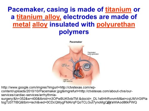
In the example on slide Slide 48, the pacemaker casing is made of titanium or a titanium alloy, electrodes are made of metal alloy insulated with polyurethan polymers, more info in here.

Slide 49

Slide49

The second device shown in slide 49 is an implant for deaf people, whose surface in contact with human body fluids is coated with Ti. More info on how this implant works can be found in here.
Slide 50Slide50The insulin pump shown in slide 50 is a schematic of the pump controlled electronically by a control algorithm device, a sensor, an electronic receiver that connects with an iPhone through an wireless channel.
Slide 51Slide51

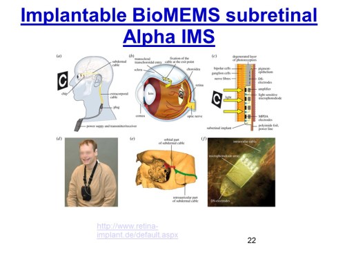
The prosthetic retina on slide 51 is an example of a bio-MEMS based optical sensor that takes the outside image through a tiny camera, the electrical signal of the camera is sent to a receiver and then to an array of micro-electrodes tacked to the retina which send electrical impulses to the brain through the optical nerve. More details can be found in here.

Slide 52Slide52Slide 52 describes how easily available bio-compatible metal powders
can revolutionize 3D printing for medical implants. The surgical implants need to generate expected responses from neighboring cells and tissues. Cell behavior (adhesion, functional alteration, morphological changes, and proliferation) is strongly affected by the surgical implants’ surface properties. Surface topography, surface chemistry, and surface energy influence decisively the biological response to an implanted device.
The well controlled 3D printing atmosphere (neutral gases and restricted oxygen) guarantees the high purity of the 3D printed parts and preserves the materials’ properties.
The advantages of 3D printing for medical applications is thoroughly discussed in here.

Slide 53Slide53

Slide 53 shows five conclusions of the presentation, in which 1) many engineered metals are mechanically resistant in human body, but prone to certain corrosion if not coated,
2) Ti, Zr coated bio-ceramics are bio-compatible materials in human body, 3) medical devices implants and MEMS are useful as heart stent, orthopedic prosthetic, prosthetic retina, 3) M3DP has low costs, high quality, long life cycle and 4) Metal/bio-ceramic and Vivos dental’s synthetic bone for oral augmentation is a solution for today’s dental health care.
Slide 54Slide54Slide 54 shows conclusions regarding the hardware of the presentation, in which: 6) there are two types of metal 3D printing hardware for medical applications: Selective Laser Melting / Selective Laser Sintering, and 3D Bioploter (metal powder mixed with binder and further thermal treatment to remove binder and sinter the metallic matrix in a solid object that can be used as a replacement. Thank you for your attention!

Read Full Post »

Older Posts »