Feeds:
Posts
Comments

Posts Tagged ‘3-D printing’

High resolution 3-D optics

Curator: Larry H. Bernstein, MD, FCAP


MIT invention could boost resolution of 3-D depth cameras 1,000-fold

Imagine 3-D depth cameras built into cellphones, 3-D printing replicas, and driverless cars with clear vision in rain, snow, or fog
By combining the information from the Kinect depth frame in (a) with polarized photographs, MIT researchers reconstructed the 3-D surface shown in (c). Polarization cues can allow coarse depth sensors like Kinect to achieve laser scan quality (b). (credit: courtesy of the researchers)

MIT researchers have shown that by exploiting light polarization (as in polarized sunglasses) they can increase the resolution of conventional 3-D imaging devices such as the Microsoft Kinect as much as 1,000 times.

The technique could lead to high-quality 3-D cameras built into cellphones, and perhaps the ability to snap a photo of an object and then use a 3-D printer to produce a replica. Further out, the work could also help the development of driverless cars.

Headed Ramesh Raskar, associate professor of media arts and sciences in the MIT Media Lab, the researchers describe the new system, which they call Polarized 3D, in a paper they’re presenting at the International Conference on Computer Vision in December.

How polarized light works

If an electromagnetic wave can be thought of as an undulating squiggle, polarization refers to the squiggle’s orientation. It could be undulating up and down, or side to side, or somewhere in-between.

Polarization also affects the way in which light bounces off of physical objects. If light strikes an object squarely, much of it will be absorbed, but whatever reflects back will have the same mix of polarizations (horizontal and vertical) that the incoming light did. At wider angles of reflection, however, light within a certain range of polarizations is more likely to be reflected.

This is why polarized sunglasses are good at cutting out glare: Light from the sun bouncing off asphalt or water at a low angle features an unusually heavy concentration of light with a particular polarization. So the polarization of reflected light carries information about the geometry of the objects it has struck.

This relationship has been known for centuries, but it’s been hard to do anything with it, because of a fundamental ambiguity about polarized light. Light with a particular polarization, reflecting off of a surface with a particular orientation and passing through a polarizing lens is indistinguishable from light with the opposite polarization, reflecting off of a surface with the opposite orientation.

This means that for any surface in a visual scene, measurements based on polarized light offer two equally plausible hypotheses about its orientation. Canvassing all the possible combinations of either of the two orientations of every surface, in order to identify the one that makes the most sense geometrically, is a prohibitively time-consuming computation.

Polarization plus depth sensing

To resolve this ambiguity, the Media Lab researchers use coarse depth estimates provided by some other method, such as the time a light signal takes to reflect off of an object and return to its source. Even with this added information, calculating surface orientation from measurements of polarized light is complicated, but it can be done in real-time by a graphics processing unit, the type of special-purpose graphics chip found in most video game consoles.

The researchers’ experimental setup consisted of a Microsoft Kinect — which gauges depth using reflection time — with an ordinary polarizing photographic lens placed in front of its camera. In each experiment, the researchers took three photos of an object, rotating the polarizing filter each time, and their algorithms compared the light intensities of the resulting images.

On its own, at a distance of several meters, the Kinect can resolve physical features as small as a centimeter or so across. But with the addition of the polarization information, the researchers’ system could resolve features in the range of hundreds of micrometers, or one-thousandth the size.

For comparison, the researchers also imaged several of their test objects with a high-precision laser scanner, which requires that the object be inserted into the scanner bed. Polarized 3D still offered the higher resolution.

Uses in cameras and self-driving cars

A mechanically rotated polarization filter would probably be impractical in a cellphone camera, but grids of tiny polarization filters that can overlay individual pixels in a light sensor are commercially available. Capturing three pixels’ worth of light for each image pixel would reduce a cellphone camera’s resolution, but no more than the color filters that existing cameras already use.

The new paper also offers the tantalizing prospect that polarization systems could aid the development of self-driving cars. Today’s experimental self-driving cars are, in fact, highly reliable under normal illumination conditions, but their vision algorithms go haywire in rain, snow, or fog.

That’s because water particles in the air scatter light in unpredictable ways, making it much harder to interpret. The MIT researchers show that in some very simple test cases their system can exploit information contained in interfering waves of light to handle scattering.


Abstract of Polarized 3D: High-Quality Depth Sensing with Polarization Cues

Coarse depth maps can be enhanced by using the shape information from polarization cues. We propose a framework to combine surface normals from polarization (hereafter polarization normals) with an aligned depth map. Polarization normals have not been used for depth enhancement before. This is because polarization normals suffer from physics-based artifacts, such as azimuthal ambiguity, refractive distortion and fronto-parallel signal degradation. We propose a framework to overcome these key challenges, allowing the benefits of polarization to be used to enhance depth maps. Our results demonstrate improvement with respect to state-of-the-art 3D reconstruction techniques

Read Full Post »

Carnegie Scientists 3-D print a heart

Curator: Larry H. Bernstein, MD, FCAP


How to 3-D print a heart

October 23, 2015

http://www.kurzweilai.net/how-to-3-d-print-a-heart?utm_source=KurzweilAI+Weekly+Newsletter_147a5a48c1-9a20162408-282099089

Carnegie Mellon scientists are creating cutting-edge technology that could one day solve the shortage of heart transplants, which are currently needed to repair damaged organs.

“We’ve been able to take MRI images of coronary arteries and 3-D images of embryonic hearts and 3-D bioprint them with unprecedented resolution and quality out of very soft materials like collagens, alginates and fibrins,” said Adam Feinberg, an associate professor of Materials Science and Engineering and Biomedical Engineering at Carnegie Mellon University.

Feinberg leads the Regenerative Biomaterials and Therapeutics Group, and the group’s study was published in an open-access paper today (Oct. 23) in the journal Science Advances.

https://youtu.be/Zfl_tFdt2D4
College of Engineering, Carnegie Mellon University | Adam Feinberg Demonstrates 3-D Bioprinting Process

“The challenge with soft materials is that they collapse under their own weight when 3-D printed in air,” explained Feinberg. “So we developed a method of printing these soft materials inside a support bath material. Essentially, we print one gel inside of another gel, which allows us to accurately position the soft material as it’s being printed, layer-by-layer.”

A FRESH idea

With this new FRESH (Freeform Reversible Embedding of Suspended Hydrogels) technique, after printing, the support gel can be easily melted away and removed by heating to body temperature, which does not damage the delicate biological molecules or living cells that were bioprinted.

As a next step, the group is working toward incorporating real heart cells into these 3-D printed tissue structures, providing a scaffold to help form contractile muscle.

Accessible bioprinters

Most 3-D bioprinters cost more than $100,000 and/or require specialized expertise to operate, limiting wider-spread adoption. Feinberg’s group, however, has been able to implement their technique on a range of consumer-level 3-D printers, which cost less than $1,000 and use open-source hardware and software.

“Not only is the cost low, but by using open-source software, we have access to fine-tune the print parameters, optimize what we’re doing, and maximize the quality of what we’re printing,” Feinberg said.

More than 4,000 Americans are currently on the waiting list to receive a heart transplant. With failing hearts, these patients have no other options; heart tissue, unlike other parts of the body, is unable to heal itself once it is damaged.


Abstract of Three-dimensional printing of complex biological structures by freeform reversible embedding of suspended hydrogels

We demonstrate the additive manufacturing of complex three-dimensional (3D) biological structures using soft protein and polysaccharide hydrogels that are challenging or impossible to create using traditional fabrication approaches. These structures are built by embedding the printed hydrogel within a secondary hydrogel that serves as a temporary, thermoreversible, and biocompatible support. This process, termed freeform reversible embedding of suspended hydrogels, enables 3D printing of hydrated materials with an elastic modulus <500 kPa including alginate, collagen, and fibrin. Computer-aided design models of 3D optical, computed tomography, and magnetic resonance imaging data were 3D printed at a resolution of ~200 μm and at low cost by leveraging open-source hardware and software tools. Proof-of-concept structures based on femurs, branched coronary arteries, trabeculated embryonic hearts, and human brains were mechanically robust and recreated complex 3D internal and external anatomical architectures.

Read Full Post »

The Scientist Who Is Making 3D Printing More Human

Curator: Larry H. Bernstein, MD, FCAP


The Scientist Who Is Making 3D Printing More Human Madeline Gannon Wants To Unlock The Designer In All Of Us

Popular Science http://www.popsci.com/scientist-who-is-making-3d-printing-more-human

Madeline Gannon is a researcher, teacher at the Carnegie Mellon University School of Architecture and Ph.D. candidate in Computational Design — but that’s not all. She is on a mission to open up the infinite design possibilities of 3D printing to the world.

“Currently you have to have a lot of technical background in order to participate in creating things for 3D printers,” Gannon says. “There is still a huge knowledge barrier for how we create digital models.”

As the technology has advanced, prices have plummeted, and now anyone can buy a 3D printer for a few hundred dollars, Gannon notes. However, not just anyone can create original designs for 3D-printed artifacts.

To put true creative power into the hands of any ordinary 3D printer owner, Gannon has developed an innovative new system called “Tactum.”

DESIGN WITHIN REACH

Tactum is a new type of software that lets users create their own unique designs for 3D printers by simply touching a projected image.

Using their innate hand gestures, someone using Tactum can poke, rub and otherwise manipulate the projected image that will become their 3D printed object, and see it instantly change shape in response.

In keeping with the goal of democratizing the process, Gannon designed her first series of Tactum artifacts on a surface that everyone can access freely and manipulate instinctively, that being the human body.

“My goal was to bring the digital out to the physical world and out onto your body,” says Gannon.

Along with a companion project called Reverb — which translates these user-created designs into printable meshes — that impulse has resulted in a spectacular diversity of bracelet and necklace designs, ranging from smooth landscapes, intricate textures and chaotic free forms to delicate geometries derived from the 19th century art of chronography.

CRAFTING THE FUTURE

Fashion is only the beginning. The real fireworks start when Tactum is deployed for function.

Again turning to the familiar, Gannon’s first functional artifact was a custom watchband for a Motorola Moto 360 smartwatch.

One of her future goals is to use Tactum for customizing prosthetics and other wearable medical devices.

Gannon envisions doctor and patient collaborating with a Tactum technician in real time, with the patient providing instant feedback on the fit and feel of the device.

Madlab.cc

Since Tactum can potentially produce 3D-printed objects more quickly, at lower cost, doctor and patient could continually adjust a prosthetic limb as needed, while enabling a high degree of personal expression.

Tactum also has potential in the classroom, and the system reflects Gannon’s insistence on teaching tools that help learners dive right into the creative process.

“I want them to be intuitive. I want them to be easy to understand. I want to hide complexity and show abstraction,” Gannon says.

Later this year, she will be an artist-in-residence at the leading 3D software design company Autodesk Research, a collaborative supporter and the funder behind Tactum.

Gannon expects her stay at Autodesk to be “like a kid in a candy shop,” with access to every imaginable CNC fabrication device — a machine commonly used by machinists and craftspeople to create moldings and other architectural elements.

She plans to work with researchers there on applying Tactum to prosthetic devices, and to create new skin-based artifacts including, perhaps, a “full body thing.”

Based on Gannon’s work so far, the Autodesk experience is bound to result in the unique, the spectacular, and the breaking of even more barriers.

THE MAKING OF A MAKER

Gannon’s focus on opening up access to knowledge is rooted in her memories of visiting museums as a high school student.

The museum trips also inspired Gannon to pursue an academic path that eventually lead her to 3D printing and the collaborative work of her design collective, MADLAB.CC.

“In high school I went to museums, and I noticed myself admiring the building more than the exhibits,” she says. “That gave me a hint that architecture was something I wanted to get into.”

Madlab.cc

Gannon progressed all the way through to the last year of architecture school before she had an epiphany, brought on by an encounter with a CNC router. Gannon found the experience of getting instant, physical results for her designs to be “intoxicating.”

There was just one problem. Gannon soon encountered the limit of the human-computer interface, and she found herself unable to transform her thoughts into action.

“I wanted to do some weird things with it…I wanted to learn how to talk to this machine so I could do more interesting things with it,” she says.

That desire drove Gannon to immerse herself in computer science, and now she finds herself at the leading edge of the “awkward space between computer science and the design realm,” exploring the future of digital making.

Gannon sees that future as an exciting, accessible one, where “everyone is an amateur, everyone is a beginner,” and people share their knowledge in a community of creators.

“The world needs more materials scientists!” she exclaims.


Read Full Post »

What is 3-D Printing

Curator: Larry H. Bernstein, MD, FCAP


3D printing or additive manufacturing is a process of making three dimensional solid objects from a digital file. The creation of a 3D printed object is achieved using additive processes. In an additive process an object is created by laying down successive layers of material until the entire object is created. Each of these layers can be seen as a thinly sliced horizontal cross-section of the eventual object.

How does 3D printing work?

It all starts with making a virtual design of the object you want to create. This virtual design is made in a CAD (Computer Aided Design) file using a 3D modeling program (for the creation of a totally new object) or with the use of a 3D scanner (to copy an existing object). A 3D scanner makes a 3D digital copy of an object.

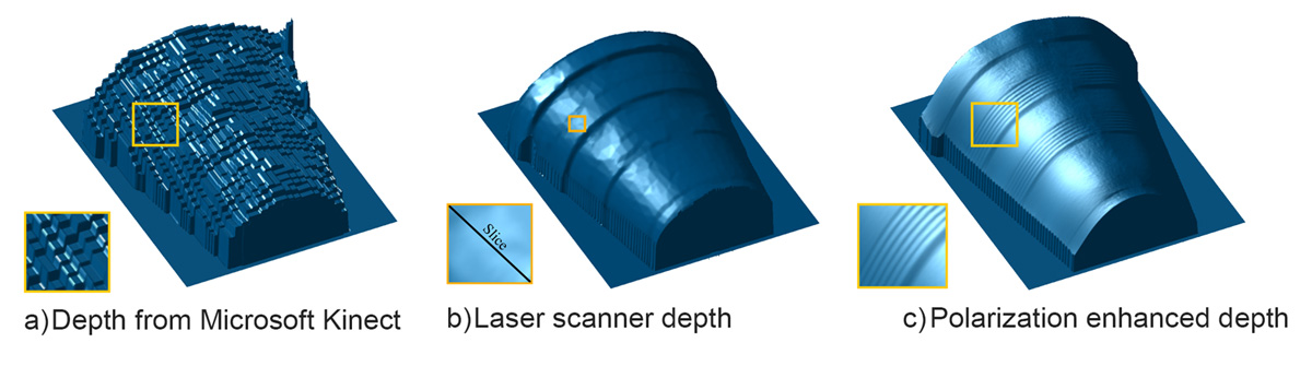
3d scanners use different technologies to generate a 3d model such as time-of-flight, structured / modulated light, volumetric scanning and many more.

Recently, many IT companies like Microsoft and Google enabled their hardware to perform 3d scanning, a great example is Microsoft’s Kinect. This is a clear sign that future hand-held devices like smartphones will have integrated 3d scanners. Digitizing real objects into 3d models will become as easy as taking a picture. Prices of 3d scanners range from very expensive professional industrial devices to 30 USD DIY devices anyone can make at home.

Below you’ll find a short demonstration of the process of 3D scanning with a professional HDI 3D scanner that uses structured light:

To prepare a digital file for printing, the 3D modeling software “slices” the final model into hundreds or thousands of horizontal layers. When the sliced file is uploaded in a 3D printer, the object can be created layer by layer. The 3D printer reads every slice (or 2D image) and creates the object, blending each layer with hardly any visible sign of the layers, with as a result the three dimensional object.

Processes and technologies

Not all 3D printers use the same technology. There are several ways to print and all those available are additive, differing mainly in the way layers are build to create the final object.
Some methods use melting or softening material to produce the layers. Selective laser sintering (SLS) and fused deposition modeling (FDM) are the most common technologies using this way of printing. Another method of printing is when we talk about curing a photo-reactive resin with a UV laser or another similar power source one layer at a time. The most common technology using this method is called stereolithography (SLA).

To be more precise: since 2010, the American Society for Testing and Materials (ASTM) group “ASTM F42 – Additive Manufacturing”, developed a set of standards that classify the Additive Manufacturing processes into 7 categories  according to Standard Terminology for Additive Manufacturing Technologies. These seven processes are:

  1. Vat Photopolymerisation
  2. Material Jetting
  3. Binder Jetting
  4. Material Extrusion
  5. Powder Bed Fusion
  6. Sheet Lamination
  7. Directed Energy Deposition

Below you’ll find a short explanation of all of seven processes for 3d printing:

Vat Photopolymerisation

A 3D printer based on the Vat Photopolymerisation method has a container filled with photopolymer resin which is then hardened with UV light source.

Vat photopolymerisation schematics. Image source: lboro.ac.uk

The most commonly used technology in this processes is Stereolithography (SLA). This technology employs a vat of liquid ultraviolet curable photopolymer resin and an ultraviolet laser to build the object’s layers one at a time. For each layer, the laser beam traces a cross-section of the part pattern on the surface of the liquid resin. Exposure to the ultraviolet laser light cures and solidifies the pattern traced on the resin and joins it to the layer below.

After the pattern has been traced, the SLA’s elevator platform descends by a distance equal to the thickness of a single layer, typically 0.05 mm to 0.15 mm (0.002″ to 0.006″). Then, a resin-filled blade sweeps across the cross section of the part, re-coating it with fresh material. On this new liquid surface, the subsequent layer pattern is traced, joining the previous layer. The complete three dimensional object is formed by this project. Stereolithography requires the use of supporting structures which serve to attach the part to the elevator platform and to hold the object because it floats in the basin filled with liquid  resin. These are removed manually after the object is finished.

This technique was invented in 1986 by Charles Hull, who also at the time founded the company, 3D Systems.

Animation of the SLA process

Other technologies using Vat Photopolymerisation are the new ultrafast Continuous Liquid Interface Productionor CLIP and marginally used older Film Transfer Imaging and Solid Ground Curing.

Material Jetting

In this process, material is applied in droplets through a small diameter nozzle, similar to the way a common inkjet paper printer works, but it is applied layer-by-layer to a build platform making a 3D object and then hardened by UV light.

Material Jetting schematics. Image source: CustomPartNet

Here you can see presentation of Stratasys’ Objet500 Connex 3D printers that use their proprietary Triple-Jetting technology where you can clearly see the printheads and UV light:

Binder Jetting

With binder jetting two materials are used: powder base material and a liquid binder. In the build chamber, powder is spread in equal layers and binder is applied through jet nozzles that “glue” the powder particles in the shape of a programmed 3D object. The finished object is “glued together” by binder remains in the container with the powder base material. After the print is finished, the remaining powder is cleaned off and used for 3D printing the next object. This technology was first developed at the Massachusetts Institute of Technology in 1993 and in 1995 Z Corporation obtained an exclusive license.

Binder jetting 3D printing technology overview. Image source: additively.com

The following video shows a high-end binder jetting based 3D printer, the ExOne M-Flex.  This 3D printer uses metal powder and curing after the binding material is applied.

Material Extrusion

The most commonly used technology in this process is Fused deposition modeling (FDM)

Fused deposition modelling (FDM), a method of rapid prototyping: 1 – nozzle ejecting molten material (plastic), 2 – deposited material (modelled part), 3 – controlled movable table. Image source: Wikipedia, made by user Zureks under CC Attribution-Share Alike 4.0 International license.

The FDM technology works using a plastic filament or metal wire which is unwound from a coil and supplying material to an extrusion nozzle which can turn the flow on and off. The nozzle is heated to melt the material and can be moved in both horizontal and vertical directions by a numerically controlled mechanism, directly controlled by a computer-aided manufacturing (CAM) software package. The object is produced by extruding melted material to form layers as the material hardens immediately after extrusion from the nozzle. This technology is most widely used with two plastic filament material types: ABS (Acrylonitrile Butadiene Styrene) and PLA (Polylactic acid) but many other materials are available ranging in properties from wood filed, conductive, flexible etc.

FDM was invented by Scott Crump in the late 80’s. After patenting this technology he started the company Stratasysin 1988. The software that comes with this technology automatically generates support structures if required. The machine dispenses two materials, one for the model and one for a disposable support structure.

The term fused deposition modeling and its abbreviation to FDM are trademarked by Stratasys Inc. The exactly equivalent term, fused filament fabrication (FFF), was coined by the members of the RepRap project to give a phrase that would be legally unconstrained in its use.

Animation of the FDM process

Powder Bed Fusion

The most commonly used technology in this processes is Selective laser sintering (SLS)

SLS system schematic. Image source: Wikipedia from user Materialgeeza under Creative Commons Attribution-Share Alike 3.0 Unported license

This technology uses a high power laser to fuse small particles of plastic, metal, ceramic or glass powders into a mass that has the desired three dimensional shape. The laser selectively fuses the powdered material by scanning the cross-sections (or layers) generated by the 3D modeling program on the surface of a powder bed. After each cross-section is scanned, the powder bed is lowered by one layer thickness. Then a new layer of material is applied on top and the process is repeated until the object is completed.

All untouched powder remains as it is and becomes a support structure for the object. Therefore there is no need for any support structure which is an advantage over SLS and SLA. All unused powder can be used for the next print. SLS was developed and patented by Dr. Carl Deckard at the University of Texas in the mid-1980s, under sponsorship of DARPA.

Animation of the SLS process

Sheet Lamination

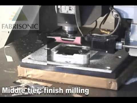
Sheet lamination involves material in sheets which is bound together with external force. Sheets can be metal, paper or a form of polymer. Metal sheets are welded together by ultrasonic welding in layers and then CNC milled into a proper shape. Paper sheets can be used also, but they are glued by adhesive glue and cut in shape by precise blades. A leading company in this field is Mcor Technologies.

Simplified model of ultrasonic sheet metal 3D printing. Image source: Wikipedia from user Mmrjf3 shared under Creative Commons Attribution 3.0 Unported license.

Here is a video with a metal sheet 3D printer by Fabrisonic that uses additive manufacturing paired with CNC milling:

… and here is an overview of Mcor 3D printers that use standard A4 paper sheets:

Directed Energy Deposition

This process is mostly used in the high-tech metal industry and in rapid manufacturing applications. The 3D printing apparatus is usually attached to a multi-axis robotic arm and consists of a nozzle that deposits metal powder or wire on a surface and an energy source (laser, electron beam or plasma arc) that melts it, forming a solid object.

Direct Energy Deposition with metal powder and laser melting. Image source: Merlin project

Sciaky is a major tech company in this area and here is their video presentation showing electron beam additive manufacturing:


http://i.ytimg.com/vi/5s0J-7W4i6s/hqdefault.jpg

http://i.ytimg.com/vi/Xff4eIYXDvI/hqdefault.jpg


Examples & applications of 3D printing

http://i.ytimg.com/vi/A10XEZvkgbY/hqdefault.jpg

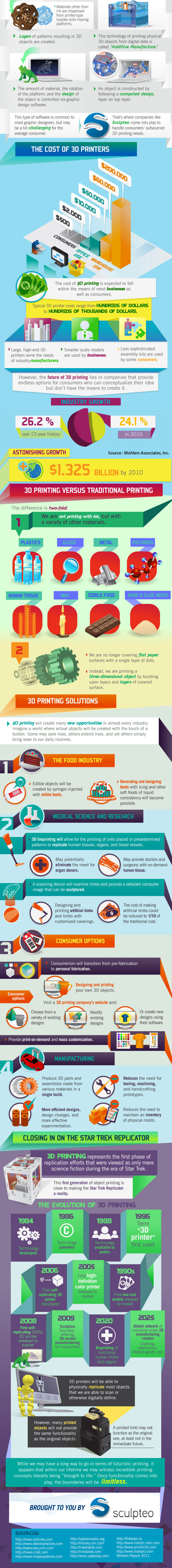
http://3dprinting.com/wp-content/uploads/2012/06/3dprinting-Infographic.jpg


Applications include rapid prototyping, architectural scale models & maquettes, healthcare (3d printed prosthetics and printing with human tissue) and entertainment (e.g. film props).

Other examples of 3D printing would include reconstructing fossils in paleontology, replicating ancient artifacts in archaeology, reconstructing bones and body parts in forensic pathology and reconstructing heavily damaged evidence acquired from crime scene investigations.

3D printing industry

The worldwide 3D printing industry is expected to grow from $3.07B in revenue in 2013 to $12.8B by 2018, and exceed $21B in worldwide revenue by 2020. As it evolves, 3D printing technology is destined to transform almost every major industry and change the way we live, work, and play in the future.
Source: Wohlers Report 2015

Medical industry

The outlook for medical use of 3D printing is evolving at an extremely rapid pace as specialists are beginning to utilize 3D printing in more advanced ways. Patients around the world are experiencing improved quality of care through 3D printed implants and prosthetics never before seen.

Bio-printing

As of the early two-thousands 3D printing technology has been studied by biotech firms and academia for possible use in tissue engineering applications where organs and body parts are built using inkjet techniques. Layers of living cells are deposited onto a gel medium and slowly built up to form three dimensional structures. We refer to this field of research with the term: bio-printing.

Aerospace & aviation industries

The growth in utilisation of 3D printing in the aerospace and aviation industries can, for a large part, be derived from the developments in the metal additive manufacturing sector.
NASA for instance prints combustion chamber liners using selective laser melting and as of march 2015 the FAA cleared GE Aviation’s first 3D printed jet engine part to fly: a laser sintered housing for a compressor inlet temperature sensor.

Automotive industry

Although the automotive industry was among the earliest adopters of 3D printing it has for decades relegated 3d printing technology to low volume prototyping applications.
Nowadays the use of 3D printing in automotive is evolving from relatively simple concept models for fit and finish checks and design verification, to functional parts that are used in test vehicles, engines, and platforms. The expectations are that 3D printing in the automotive industry will generate a combined $1.1 billion dollars by 2019.

Industrial printing

In the last couple of years the term 3D printing has become more known and the technology has reached a broader public. Still, most people haven’t even heard of the term while the technology has been in use for decades. Especially manufacturers have long used these printers in their design process to create prototypes for traditional manufacturing and research purposes. Using 3D printers for these purposes is called rapid prototyping.

Why use 3D printers in this process you might ask yourself. Now, fast 3D printers can be bought for tens of thousands of dollars and end up saving the companies many times that amount of money in the prototyping process. For example, Nike uses 3D printers to create multi-colored prototypes of shoes. They used to spend thousands of dollars on a prototype and wait weeks for it. Now, the cost is only in the hundreds of dollars, and changes can be made instantly on the computer and the prototype reprinted on the same day.

Besides rapid prototyping, 3D printing is also used for rapid manufacturing. Rapid manufacturing is a new method of manufacturing where companies are using 3D printers for short run custom manufacturing. In this way of manufacturing the printed objects are not prototypes but the actual end user product. Here you can expect more availability of personally customized products.

Personal printing

Personal 3D printing or domestic 3D printing is mainly for hobbyists and enthusiasts and really started growing in 2011. Because of rapid development within this new market printers are getting cheaper and cheaper, with prices typically in the range of $250 – $2,500. This puts 3D printers into more and more hands.

The RepRap open source project really ignited this hobbyist market. For about a thousand dollars people could buy the RepRap kit and assemble their own desktop 3D printer. Everybody working on the RepRap shares their knowledge so other people can use it and improve it again.

History

In the history of manufacturing, subtractive methods have often come first. The province of machining (generating exact shapes with high precision) was generally a subtractive affair, from filing and turning through milling and grinding.

Additive manufacturing’s earliest applications have been on the toolroom end of the manufacturing spectrum. For example, rapid prototyping was one of the earliest additive variants and its mission was to reduce the lead time and cost of developing prototypes of new parts and devices, which was earlier only done with subtractive toolroom methods (typically slowly and expensively). However, as the years go by and technology continually advances, additive methods are moving ever further into the production end of manufacturing. Parts that formerly were the sole province of subtractive methods can now in some cases be made more profitably via additive ones.

However, the real integration of the newer additive technologies into commercial production is essentially a matter of complementing subtractive methods rather than displacing them entirely. Predictions for the future of commercial manufacturing, starting from today’s already- begun infancy period, are that manufacturing firms will need to be flexible, ever-improving users of all available technologies in order to remain competitive.

Future

It is predicted by some additive manufacturing advocates that this technological development will change the nature of commerce, because end users will be able to do much of their own manufacturing rather than engaging in trade to buy products from other people and corporations.

3D printers capable of outputting in colour and multiple materials already exist and will continue to improve to a point where functional products will be able to be output. With effects on energy use, waste reduction, customization, product availability, medicine, art, construction and sciences, 3D printing will change the manufacturing world as we know it.

If you’re interested in more future predictions regarding 3D printing, check out The Future Of Open Fabrication.

Services

Not everybody can afford or is willing to buy their own 3D printer. Does this mean you cannot enjoy the possibilities of 3D printing? No, not to worry. There are 3D printing service bureaus like ShapewaysPonoko and Sculpteo that can very inexpensively print and deliver an object from a digital file that you simply upload to their website. You can even sell your 3D designs on their website and make a little money out of it!

There are also companies who offer their services business-to-business. When, for instance, you have an architecture practice and you need to build model scales, it is very time consuming doing this the old fashioned way. There are services where you can send your digital model to and they print the building on scale for you to use in client presentations. These kind of services can already be found in a lot of different industries like dental, medical, entertainment and art.

3D Marketplaces

If you don’t have the skills to design your own 3D models, you can still print some very nice objects. 3D marketplaces such as Pinshape and CGTrader contain 3d model files you can download for a small charge or for free.


Read Full Post »

3-D Printing

3-D Printing

Curator: Larry H. Bernstein, MD, FCAP


3-D Printing

For methods of applying a 2D image on a 3D surface, see pad printing. For methods of copying 2D parallax stereograms that seem 3D to the eye, see lenticular printing and holography.

MakerBot 3d Printer

3D printing also known as additive manufacturing is any of various processes used to make a three-dimensional object.[1] In 3D printing, additive processes are used, in which successive layers of material are laid down under computer control.[2] These objects can be of almost any shape or geometry, and are produced from a 3D model or other electronic data source. A 3D printer is a type of industrial robot.

3D printing in the term’s original sense refers to processes that sequentially deposit material onto a powder bed with inkjet printer heads. More recently the meaning of the term has expanded to encompass a wider variety of techniques such as extrusion and sintering based processes. Technical standards generally use the term additive manufacturing for this broader sense.

Earlier Additive Manufacturing (AM) equipment and materials were developed in the 1980s.[3] In 1981, Hideo Kodama of Nagoya Municipal Industrial Research Institute invented two AM fabricating methods of a three-dimensional plastic model with photo-hardening polymer, where the UV exposure area is controlled by a mask pattern or the scanning fiber transmitter.[4][5] Then in 1984, Chuck Hull of 3D Systems Corporation[6] developed a prototype system based on this process known as stereolithography, in which layers are added by curing photopolymers with ultraviolet light lasers. Hull defined the process as a “system for generating three-dimensional objects by creating a cross-sectional pattern of the object to be formed,”[7][8] but this had been already invented by Kodama. Hull’s contribution is the design of the STL (STereoLithography) file format widely accepted by 3D printing software as well as the digital slicing and infill strategies common to many processes today. The term 3D printing originally referred to a process employing standard and custom inkjet print heads. The technology used by most 3D printers to date—especially hobbyist and consumer-oriented models—is fused deposition modeling, a special application of plastic extrusion.

AM processes for metal sintering or melting (such as selective laser sinteringdirect metal laser sintering, and selective laser melting) usually went by their own individual names in the 1980s and 1990s. Nearly all metalworking production at the time was by castingfabricationstamping, and machining; even though plenty of automation was applied to those technologies (such as by robot welding and CNC), the idea of a tool or head moving through a 3D work envelope transforming a mass of raw material into a desired shape layer by layer was associated by most people only with processes that removed metal (rather than adding it), such as CNC milling, CNC EDM, and many others. But AM-type sintering was beginning to challenge that assumption. By the mid 1990s, new techniques for material deposition were developed at Stanford and Carnegie Mellon University, including microcasting[9] and sprayed materials.[10] Sacrificial and support materials had also become more common, enabling new object geometries.[11]

The umbrella term additive manufacturing gained wider currency in the decade of the 2000s[12] as the various additive processes matured and it became clear that soon metal removal would no longer be the only metalworking process done under that type of control (a tool or head moving through a 3D work envelope transforming a mass of raw material into a desired shape layer by layer). It was during this decade that the term subtractive manufacturing appeared as a retronym for the large family of machining processes with metal removal as their common theme. However, at the time, the term 3D printing still referred only to the polymer technologies in most minds, and the term AM was likelier to be used in metalworking contexts than among polymer/inkjet/stereolithography enthusiasts. The term subtractive has not replaced the termmachining, instead complementing it when a term that covers any removal method is needed.

By the early 2010s, the terms 3D printing and additive manufacturing developed senses in which they were synonymous umbrella terms for all AM technologies. Although this was a departure from their earlier technically narrower senses, it reflects the simple fact that the technologies all share the common theme of sequential-layer material addition/joining throughout a 3D work envelope under automated control. (Other terms that have appeared, which are usually used as AM synonyms (although sometimes as hypernyms), have been desktop manufacturingrapid manufacturing [as the logical production-level successor to rapid prototyping], and on-demand manufacturing [which echoes on-demand printing in the 2D sense of printing].) The 2010s were the first decade in which metal parts such as engine brackets[13] and large nuts[14] would be grown (either before or instead of machining) in job production rather than obligately being machined from bar stock or plate.

With the maturation of the technology, several authors had begun to speculate that 3-D printing could aid in sustainable development in the developing world.[15][16][17]


Modeling3D modeling

https://upload.wikimedia.org/wikipedia/commons/thumb/9/9c/Rapid_prototyping_slicing.jpg/220px-Rapid_prototyping_slicing.jpg

https://upload.wikimedia.org/wikipedia/commons/thumb/5/5d/Hyperboloid_Print.ogv/300px–Hyperboloid_Print.ogv.jpg

3D printable models may be created with a computer aided design (CAD) package or via a 3D scanner or via a plain digital camera and photogrammetry software.

The manual modeling process of preparing geometric data for 3D computer graphics is similar to plastic arts such as sculpting. 3D scanning is a process of analysing and collecting digital data on the shape and appearance of a real object. Based on this data, three-dimensional models of the scanned object can then be produced.

Regardless of the 3D modeling software used, the 3D model (often in .skp, .dae, .3ds or some other format) then needs to be converted to either a .STL or a .OBJ format, to allow the printing (a.k.a. “CAM”) software to be able to read it.

https://en.wikipedia.org/wiki/3D_printing

Read Full Post »

Drug ‘Chemputer’

Curator: Larry H Bernstein, MD, FCAP


Revised 9/30/2015


The ‘chemputer’ that could print out any drug

When Lee Cronin learned about the concept of 3D printers, he had a brilliant idea: why not turn such a device into a universal chemistry set that could make its own drugs?

http://www.theguardian.com/science/2012/jul/21/chemputer-that-prints-out-drugs


Professor Lee Cronin is a likably impatient presence, a one-man catalyst. “I just want to get stuff done fast,” he says. And: “I am a control freak in rehab.” Cronin, 39, is the leader of a world-class team of 45 researchers at Glasgow University, primarily making complex molecules. But that is not the extent of his ambition. A couple of years ago, at a TED conference, he described one goal as the creation of “inorganic life”, and went on to detail his efforts to generate “evolutionary algorithms” in inert matter. He still hopes to “create life” in the next year or two.

At the same time, one branch of that thinking has itself evolved into a new project: the notion of creating downloadable chemistry, with the ultimate aim of allowing people to “print” their own pharmaceuticals at home. Cronin’s latest TEDtalk asked the question: “Could we make a really cool universal chemistry set? Can we ‘app’ chemistry?” “Basically,” he tells me, in his office at the university, with half a grin, “what Apple did for music, I’d like to do for the discovery and distribution of prescription drugs.”

The idea is very much at the conception stage, but as he walks me around his labs Cronin begins to outline how that “paradigm-changing” project might progress. He has been in Scotland for 10 years and in that time he has worked hard, as any chemist worth his salt should, to get the right mix of people to produce the results he wants. Cronin’s interest has always been in complex chemicals and the origins of life. “We are pretty good at making molecules. We do a lot of self-assembly at a molecular level,” he says. “We are able to make really large molecules and I was able to get a lot of money in grants and so on for doing that.” But after a while, Cronin suggests, making complex molecules for their own sake can seem a bit limiting. He wanted to find some more life-changing applications for his team’s expertise.

A couple of years ago, Cronin was invited to an architectural seminar to discuss his work on inorganic structures. He had been looking at the way crystals grew “inorganic gardens” of tube-like structures between themselves. Among the other speakers at that conference was a man explaining the possibilities of 3D printing for conventional architectural forms. Cronin wondered if you could apply this 3D principle to structures at a molecular level. “I didn’t want to print an aeroplane, or a jaw bone,” he says. “I wanted to do chemistry.”

Advertisement

Cronin prides himself on his lateral thinking; his gift for chemistry came fairly late – he stumbled through comprehensive school in Ipswich and initially university – before realising a vocation for molecular chemistry that has seen him make a series of prize-winning, and fund-generating, advances in the field. He often puts his faith in counterintuition. “Confusions of ideas produce discovery,” he says. “People, researchers, always come to me and say they are pretty good at thinking outside the box and I usually think ‘yes, but it is a pretty small box’.” In analyzing how to apply 3D printing to chemistry, Cronin wondered in the first instance if the essentially passive idea of a highly sophisticated form of copying from a software blueprint could be made more dynamic. In his lab, they put together a rudimentary prototype of a chemical 3D printer, which could be programmed to make basic chemical reactions to produce different molecules.


First Complete Structural Study Of A Pegylated Protein

http://www.technologynetworks.com/Proteomics/news.aspx?ID=183266

Significant data obtained at NUI Galway reports first crystal structure of a protein modified with a single PEG chain.

Protein PEGylation is a technique routinely used to improve the pharmacological properties of injectable therapeutic proteins. PEG stands for polyethylene glycol, a synthetic polymer that is attached to proteins. The PEG chain artificially increases the size of the protein and improves its retention in the bloodstream. By remaining longer in the blood stream the protein therapeutic is more effective than normal.

Since PEGylation was developed in the 1970s, PEGylated proteins have significantly improved the treatment of several chronic diseases, including hepatitis C, leukemia, arthritis, and Crohn’s disease. PEGylated interferon is one of the most powerful therapeutics used to treat chronic hepatitis. Despite their importance the structure of PEGylated proteins has remained elusive. Now the first crystal structure of a protein modified with a single PEG chain has been determined through research at NUI Galway.

This important research was developed at NUI Galway by Italian PhD student Giada Cattani working with Dr. Peter Crowley, the lead author of the paper. The work also involved collaboration with Dr. Lutz Vogeley from the School of Biochemistry and Immunology at Trinity College Dublin and the crucial X-ray data was collected at the Diamond synchrotron in Oxford, UK.

Commenting on the research findings Dr. Peter Crowley from the School of Chemistry, NUI Galway commented, “The crystal structure reveals an extraordinary double helical arrangement of the protein! It is significant that this data was obtained at NUI Galway, the only Irish University to offer a degree programme in Biopharmaceutical Chemistry. This attractive programme provides training in an area that is essential for the development of new medicines and contributes to the Irish economy.”

A common approach to understand proteins is to crystallize them and determine their structure by using X-ray crystallography. This is necessary to understand what the protein looks like and how it functions. Thousands of research papers have been published about PEGylated proteins. Until the recent findings at NUI Galway there had been no success in  crystallizing a PEGylated protein. The knowledge obtained by the Crowley lab has implications for understanding how PEGylated proteins work. The NUI Galway team is also looking at ways to engineer protein assemblies based on this result.


Drugs Go Under Cover as Platelets to Destroy Cancer

  • Scientists say they have for the first time developed a technique that coats anticancer drugs in membranes made from a patient’s own platelets, allowing the drugs to last longer in the body and attack both primary cancer tumors and the circulating tumor cells that can cause a cancer to metastasize. The work reportedly was tested successfully in an animal model.
  • “There are two key advantages to using platelet membranes to coat anticancer drugs,” says Zhen Gu, Ph.D., corresponding author of a paper on the work and an assistant professor in the joint biomedical engineering program at North Carolina State University and the University of North Carolina at Chapel Hill. “First, the surface of cancer cells has an affinity for platelets; they stick to each other. Second, because the platelets come from the patient’s own body, the drug carriers aren’t identified as foreign objects, so last longer in the bloodstream.”
  • “This combination of features means that the drugs can not only attack the main tumor site, but are more likely to find and attach themselves to tumor cells circulating in the bloodstream, essentially attacking new tumors before they start,” adds Quanyin Hu, a Ph.D. student and lead author of the paper (“Anticancer Platelet-Mimicking Nanovehicles”), which appears in Advanced Materials
  • Here’s how the process works. Blood is taken from a patient (a lab mouse in the case of this research) and the platelets are collected from that blood. The isolated platelets are treated to extract the platelet membranes, which are then placed in a solution with a nanoscale gel containing the anticancer drug doxorubicin (Dox), which attacks the nucleus of a cancer cell.
  • The solution is compressed, forcing the gel through the membranes and creating nanoscale spheres made up of platelet membranes with Dox-gel cores. These spheres are then treated so that their surfaces are coated with the anticancer drug TRAIL, which is most effective at attacking the cell membranes of cancer cells.
  • When released into a patient’s bloodstream, these pseudo-platelets can circulate for up to 30 hours as compared to approximately six hours for the nanoscale vehicles without the coating. When one of the pseudo-platelets comes into contact with a tumor, three things happen more or less at the same time.
  • First, the P-Selectin proteins on the platelet membrane bind to the CD44 proteins on the surface of the cancer cell, locking it into place. Second, the TRAIL on the pseudo-platelet’s surface attacks the cancer cell membrane. Third, the nanoscale pseudo-platelet is effectively swallowed by the larger cancer cell. The acidic environment inside the cancer cell then begins to break apart the pseudo-platelet, thus freeing the Dox to attack the cancer cell’s nucleus.
  • In a study using mice, the researchers found that using Dox and TRAIL in the pseudo-platelet drug delivery system was significantly more effective against large tumors and circulating tumor cells than using Dox and TRAIL in a nano-gel delivery system without the platelet membrane.
  • “We’d like to do additional pre-clinical testing on this technique,” notes Dr. Gu. “And we think it could be used to deliver other drugs, such as those targeting cardiovascular disease, in which the platelet membrane could help us target relevant sites in the body.”

Read Full Post »

%d bloggers like this: